
Summary of Contents for Ogden ETR-9090
- Page 1 MANUAL NO. 14A SOFTWARE VERSION 3.3 AND HIGHER Model ETR-9090 Microprocessor Based SMARTER LOGIC ® Auto Tune PID Controller ® INSTRUCTION MANUAL...
-
Page 2: Section 1: Introduction
C/F and security codes are held in a non-volatile This manual contains information for the installation and memory and retained for ten years if the unit is left operation of the Ogden Model ETR-9090 auto-tuning unpowered. Batteries are not necessary. micro-processor based controller with Smarter Logic ®... -
Page 3: Section 2: Catalog Numbering System
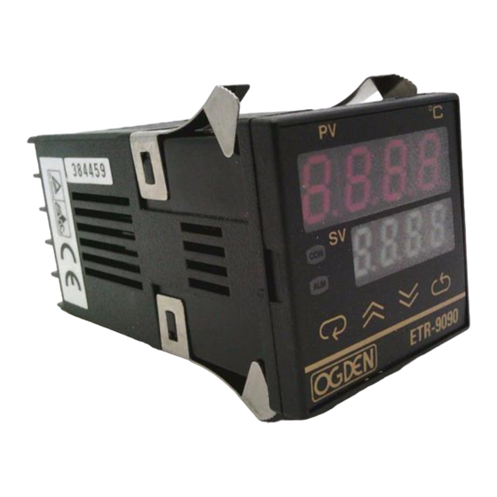
1.) With alarm relay rated 2A/240VAC 2.) No alarm Example: Standard Model: ETR-9090-1 2 1 Thermocouple Type J, K, T, E, B, R, S, N, heating relay, with alarm NOTE: A “-3” after the 9090 indicates 20-32VAC/VDC operation. A” -4” after the 9090 indicates 10-16VDC operation. - Page 4 • All control parameter and set points displayed • Output Percentage • Calibration parameters 4 PUSHBUTTONS • For ease of control set-up TOUCH KEY, Sealed mylar front panel • Splash and chemical resistant • Tactile feedback, pressure sensitive buttons MODEL ETR-9090...
-
Page 5: Section 4: Installation
• It is recommended that power to these instruments described by OSHA Standards. Units suspected of be protected by fuses and circuit breakers rated at being faulty must be removed and returned to Ogden for the minimum value possible. inspection and/or repair. They contain no user service- •... - Page 6 Power Wiring: codes. Refer to Figures 4.4, 4.5 and 4.6 on following Connect terminals as shown in Figure 4.3. The power switch S1 and Fuse F1 are included for illustrative purpose pages for sample wiring diagrams. only. All wiring must conform to national and local electrical Optional Alarm Common...
- Page 7 Thermocouple Power Heaters Solid State Relay This diagram can also be used for controls with 4-20mA output. Figure 4.5 Example of wiring connections for ETR-9090-132 with Pulsed Voltage Output for Solid State Relay Note control label for incoming power requirements.
- Page 8 Thermocouple White Coil Three Phase Heater Power Three Phase Delta Heater Heater 3-Pole Load Magnetic Fuses Contactor NEMA Figure 4.6 ETR-9090-121 with Relay Output. Heaters connected in 3-Phase to Contactor. With Alarm option. Note control label for incoming power requirements.
- Page 9 Table 4.2 Heating Output Wiring Function Internal Device: Terminals: External Connection: 1. Relay (Isolated). To line 240VAC max. Relay contact is closed during LOAD MAX 3A ON phase of output cycle. (CTRL lamp ON) 2. Current (Isolated. Input impedance of control 4-20mA Reverse acting current (The device, MAX.
-
Page 10: Section 5: Operation
Section 5: OPERATION Front Panel Adjustments Table 5.1 Keypad Operation TOUCHKEYS DESCRIPTION FUNCTION Advances the index display to the desired position. Scroll Key Indexes advanced continuously and cyclically by pressing this keypad. Increases the parameter. (Set point or other) Up Key Down Key Decreases the parameter. - Page 11 PROCESS VALUE DISPLAY Level 1 SET VALUE DISPLAY AND ADJUSTMENT Long (6 seconds) Table 5.2 Control Function and Display Flow Chart Level 2 Long (6 seconds) The "return" key ( )can be pressed at any time. Level 3 This will prompt the display to return to the Process Value/Set Value.
-
Page 12: On/Off Control
Table 5.3 Index Code (Menu) Descriptions: NOTE: Further parameter definitions (Do not disconnect power for at least 12 seconds after changing any control values. on pages 12 and 13 This allows the parameters to be entered into memory.) Index Description *Default Index Description... -
Page 13: Parameter Definitions
Table 5.4 Parameter Chart PARAMETER DEFINITIONS: PV - Process Value - This is the temperature (or other process variable) as measured at the sensor. This will indi- CONTROL cate a value within the range between the low scale value (LLiE) and High scale value (HLiE). This indication will read an error code if the temperature (process variable) goes out PARAMETER of the preset span. - Page 14 AHY1 - Hysteresis of Alarm - The value entered here ErPr - Error Protection - Sets the control and alarm defines the deadband for the alarm. The alarm will not output to be used in case of sensor failure. change state until the temperature is outside of the hYSE - Hysteresis of On-Off Control - This parameter deadband.
-
Page 15: Proportional Band
INTEGRAL ACTION PROPORTIONAL ACTION DERIVATIVE ACTION Integral Too High (Too long for recovery) Proportional Band Too Low Derivative Too Low Perfect Perfect Perfect Integral Too Low Derivative Too High Proportional Band Too High TIME TIME TIME FIG 5.1 Effects of PID Adjustment on Process Response The proportional band (Pb) is a temperature band oscillations then gradually decrease the propor- expressed in degrees. -
Page 16: Adjustment Sequence
Table 5.5 Tuning Guide ADJUSTMENT SEQUENCE: SYMPTOM: SOLUTION: 1.) Proportional Band Slow Response Decrease Proportional Band (Pb) High Overshoot or Oscillations Increase Proportional Band (Pb) 2.) Integral Time (Reset) Slow Response Increase Reset (i.e. Decrease Integral Time) Instability or Oscillations Decrease Reset (i.e. - Page 17 Table 5.7 Code Assignments and Description of Alarm Modes = SET POINT VALUE =ALARM SET POINT VALUE ALARM PROCESS HIGH ALARM PROCESS LOW ALARM DEVIATION HIGH ALARM DEVIATION LOW ALARM ASP1 ASP1 moves with SV ASP1 ASP1 moves with SV INHIBITED INHIBITED INHIBITED...
- Page 18 Ramp and Soak Function control has opened. The cycle will repeat each time the The ETR-9090 can be programmed as either a fixed set control is energized. Note Diagram No. 2 below. point controller or as a two segment ramp and soak control.
-
Page 19: Heat Transfer
Display Shift In certain applications it is desirable to shift the con- controlling value or the temperature at the sensor must be trollers indicated value from its actual value. This can be 375 degrees F. Due to the design and position of the easily accomplished with this control by using the dis- components of the system, the sensor could not be play shift function. -
Page 20: Section 6: Calibration Procedure
Section 6: CALIBRATION PROCEDURE Changing these values can make the control useless because it can be put out of calibration. Do not WARNING! attempt to re-calibrate this temperature controller unless you have an adequate calibration instrument available. This must be used to simulate the sensor input. The controller must operate under power for at least 45 3.) Press the scroll button again and the high calibration minutes before starting the calibration procedure. -
Page 21: Section 7: Troubleshooting
Do not attempt to make repairs. Also, it is advisable to use adequate packing materials to prevent damage in shipment. Return control to: OGDEN MANUFACTURING COMPANY ATTN: REPAIR DEPARTMENT 64 WEST SEEGERS ROAD ARLINGTON HEIGHTS, IL 60005... - Page 22 Table 7.1 Troubleshooting Symptom Probable Cause(s) Solution(s) 1.) LED’s will not light. —No power to instrument. —Check power line connections. —Power supply defective. —Replace power supply board. 2.) Some segments of the display or —LED display or LED Lamp defec- —Replace LED display or LED lamp.
Need help?
Do you have a question about the ETR-9090 and is the answer not in the manual?
Questions and answers