Table of Contents
Advertisement
Quick Links
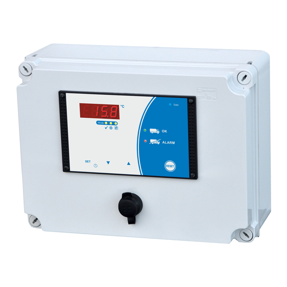
Tank monitor
TW-31
Installation and operating instructions
for plant engineering companies,
installers and service engineers
Firmware V1.9
105466 – TW-31-E - V1.9 - 06.04.2021
1. Introduction
Measuring - Controlling - Regulating
All from the same source
Programmable via
configuration software
WELBA „KONSOFT"
Page 1
Advertisement
Table of Contents

Related Manuals for WELBA TW-31


Summary of Contents for WELBA TW-31
- Page 1 Measuring - Controlling - Regulating Tank monitor All from the same source TW-31 Installation and operating instructions for plant engineering companies, installers and service engineers Firmware V1.9 Programmable via configuration software WELBA „KONSOFT" 105466 – TW-31-E - V1.9 - 06.04.2021 Page 1...
-
Page 2: Table Of Contents
5.4 Setting the date and time ....................... 26 5.5 Operation in levels ......................... 27 5.6 Operating and display elements ....................28 5.6.1 Button functions ........................ 28 5.6.2 Description of the LEDs ....................29 105466 – TW-31-E - V1.9 - 06.04.2021 Page 2... - Page 3 8.14 General measures when using electronic control systems ............68 Publisher: Welba GmbH Fon: +49 (0)2638 / 9320-0 Electronic Control Engineering Fax: +49 (0)2638 / 9320-20 Gewerbepark Siebenmorgen 6 info@welba.de D-53547 Breitscheid www.welba.de 105466 – TW-31-E - V1.9 - 06.04.2021 Page 3...
-
Page 4: Introduction
1.1 Information about this operating instructions These operating instructions are intended for the use by plant engineers, installers or service technicians of the TW-31 tank monitor. This manual contains all necessary suggestions, information, recommendations and advice for the safe and proper in- stallation and commissioning of the tank monitor. -
Page 5: Limitation Of Liability
Use of unapproved spare parts (e.g. batteries) Otherwise, our general terms and conditions as well as the terms of delivery of WELBA GmbH and the legal regulations valid at the time of conclusion of the con- tract are applicable. We reserve the right to make technical changes in the context of improving the prop- erties of use and further developments. -
Page 6: Device Description
Power failure With the integrated power pack the temperatures are monitored and stored even in the case of a power failure. Thus the TW-31 can continue its work during a power failure and activate an alarm. Data storage/-evaluation The determined data of the last 300 days (max.) temperatures, alarms, operating... -
Page 7: Type Designation
Despite all care, we point out that the use of the free PC-Software is at your own risk. NOTICE WELBA does not accept any liability for damages or loss of data resulting from the installation or use of the Software. -
Page 8: Technical Data Of Control Unit
Overvoltage category III, pollution degree I Environment specifications: - Operation temperature 0° .. +50°C - Storage temperature -20° .. +70°C - max. humidity 75% (no dew) 75% (no dew) Technical data subject to change. 105466 – TW-31-E - V1.9 - 06.04.2021 Page 8... -
Page 9: Sensor Dimensions And Technical Data
-10 .. 70° C Cabel lenght standard 2 metres A Sensors other than our standard type are available on request (dif- ferent bush form or cable length). Some of the options are shown here. 105466 – TW-31-E - V1.9 - 06.04.2021 Page 9... -
Page 10: Safety
It is essential to investigate and remedy the cause of the alarm in order to avoid harmful effects on the milk!!!!!! Even without an alarm message, the operator of the equipment has to ensure the transportability of the milk!!!! 105466 – TW-31-E - V1.9 - 06.04.2021 Page 10... - Page 11 Since the tank guard may not be opened by laypeople, the replacement DANGER! of the batteries may only be carried out by a qualified electrician DO NOT USE BATTERIES !!! EXPLOSIVE !!!!! 105466 – TW-31-E - V1.9 - 06.04.2021 Page 11...
-
Page 12: Intended Use
Please read carefully before installation and before any work on or with the tank monitor. The tank monitor TW-31 is used to monitor agitator motors, compressors and clean- ing components in milk cooling tanks in the agricultural environment for the purpose of ensuring the milk quality. -
Page 13: Safety During Installation
Connect mains supply. Lock the switch box and switch on the mains voltage. Switch on and parameterize the control as described in section “Operation”. (Possibly with the optionally available configuration Software WELBA- KONSOFT). 2.4 Wiring, screening, earthing When selecting wiring materials and installing and connecting the temperature con- troller to the electricity supply account must be taken of DIN VDE 0100 “Erection of... -
Page 14: Electrical Safety
Caution: All cables to the digital inputs must be shielded and kept as short as possible. EMC. Important note concerning the external fuse. The transformer, which is installed in the TW-31 has a two-chamber safety winding, is only conditionally short-circuit-proof due to the built-in thermal NOTICE protection. -
Page 15: Notes On Wiring
Make the connection according to the wiring diagram on the next page. Use cable bushes Make sure that cables do not chafe! Observe relay current rating! Do not wire digital inputs with external voltage! Use potential-free switches. 105466 – TW-31-E - V1.9 - 06.04.2021 Page 15... -
Page 16: Installation
In this case please contact Welba. If you keep the temperature controller for a period before using it, store it in a clean dry place at a temperature of between -20°C and +70°C. 105466 – TW-31-E - V1.9 - 06.04.2021 Page 16... -
Page 17: Fitting The Sensor
(not even within the switchbox). Temperature range sensor cable -10°C .. +70°C. The TW-31 has been designed for connection to various types of sensor (see tech- nical data). It can function properly only if one of those sensor types is installed and the parameters are correctly set. -
Page 18: Electrical Connection
Commissioning without these settings is not permitted. The guideline for the correct setting of the parameters can be found in section 7.1. 105466 – TW-31-E - V1.9 - 06.04.2021 Page 18... -
Page 19: Design Of The Control
4. Electrical connection 4.2 Design of the control The TW-31 consists of a switch box with integrated control unit 3. All necessary components for the operation are included in the switch box: 1. SMS-module (optional) 2. Agitator monitoring module (different versions) 3. -
Page 20: Automatic Detection Of The Operating Mode
Example of connecting external signalers The correct connection of the external signal transmitters and sensors is described in section 4.5. 105466 – TW-31-E - V1.9 - 06.04.2021 Page 20... -
Page 21: Error Detection (Example)
Detergent “empty” alkaline Example Error F35 -> Error is displayed, if the float switch reports “Container empty”. A listing of the predefined errors and their causes can be found in section 6.5. 105466 – TW-31-E - V1.9 - 06.04.2021 Page 21... -
Page 22: Connection Of External Signal Transmitters And Sensors
After the connection of the external signal transmitters and sensors: Test the correct wiring. To test the correct wiring the functions of the corresponding inputs can be tested in parameters “o.21” to “o.42”. 105466 – TW-31-E - V1.9 - 06.04.2021 Page 22... - Page 23 Other possible signal transmitters tank ice water cooling ice water plate head milk feed milk pump robot signal „start cooling“ pump exchanger pump roboter 105466 – TW-31-E - V1.9 - 06.04.2021 Page 23...
-
Page 24: Operation
In order to be able to assign the file to the corresponding customer when the files NOTICE are later evaluated by Welba-KONSOFT, it is important to enter the customer and tank number when installing the tank monitor. See section 7.1.1 It is recommendable to record the setting values of the tank monitor after commis- sioning or to archive them as KONSOFT files. -
Page 25: The Configuration Software Konsoft
NOTICE use. Despite all care, we point out that the use of the free PC-Software is at your own risk. WELBA does not accept any liability for damages or loss of data resulting from the installation or use of the Software. -
Page 26: Setting The Date And Time
Information: Switching to summer- / winter time NOTICE An automatic switching to summer-/winter time can be parameterized in parameter [A78]. 105466 – TW-31-E - V1.9 - 06.04.2021 Page 26... -
Page 27: Operation In Levels
The working level is used for control in everyday operation. The TW-31 is parameterized in 7 different parameter levels. The subordinate parameter levels are only entered after entering a code in or- der to avoid inadvertent adjustment of the parameters. -
Page 28: Operating And Display Elements
Service parameter I/O test parameter 5.6.1 Button functions In case of a trouble-free working process the TW-31 does not require any handling with the following exception: in case of setting the clock (see section 5.4) in case of reading and confirming error codes (see section 6.4). -
Page 29: Description Of The Leds
USB-stick inserted: Data are transferred permanent flashing USB-stick inserted: and goes off after 5 sec. Data transfer successfully completed No USB-stick inserted For the procedure for reading out the LOG files, see section 5.3 105466 – TW-31-E - V1.9 - 06.04.2021 Page 29... -
Page 30: Operation And Fault Handling
During cleaning: cleaning pump etc. - times for water intake and outlet - heating times, etc. A list of all system-alarms and their corresponding configuration can be found in section 7.5 105466 – TW-31-E - V1.9 - 06.04.2021 Page 30... - Page 31 In case of several alarms, the RESET button has to be pressed several times. See section 6.3) (Turns off when cleaning cycle runs for at least 10 minutes) System alarms is displayed only as a blinking display code 105466 – TW-31-E - V1.9 - 06.04.2021 Page 31...
-
Page 32: Milk Removal Yes Or No
Green = on = off The driver goes to the TW-31 and checks the tank monitor. If the green LED is on, milk may be drawn off. Once the milk has been taken, the driver starts the cleaning process. - Page 33 After emptying the tank the cleaning process has to be started. Only when the cleaning cycle has been active for at least 10 minutes, the tank monitor automatically resets all critical alarms. 105466 – TW-31-E - V1.9 - 06.04.2021 Page 33...
- Page 34 After emptying the tank the cleaning process has to be started. Only when the cleaning cycle has been active for at least 10 minutes, the tank monitor resets automatically all critical alarms. 105466 – TW-31-E - V1.9 - 06.04.2021 Page 34...
-
Page 35: Handling Multiple Faults
If no button is pressed for 3 seconds the display switches back to temperature and time. Only when the cleaning cycle has been active for at least 10 minutes, the tank NOTICE monitor resets automatically all critical alarms. 105466 – TW-31-E - V1.9 - 06.04.2021 Page 35... -
Page 36: Listing Fault Memory And Description
Alarm is activated if the cleaning stops earlier than the time [H32] that has been set. Agitator fault in cooling mode (milk not stirred) Alarm functions only if optional “Welba agitator monitor” is installed and parameters set [A71]. Alarm occurs after the cooling mode is started, if a backpressure by the milk has not been detected on the stirrer within the time [H40]. -
Page 37: Informative Tank Monitor Alarms (Green)
Power cut directly The alarm can function only if the optional power pack is installed. Re- gardless of the operating mode the alarm is triggered in the event of a power cut. 105466 – TW-31-E - V1.9 - 06.04.2021 Page 37... -
Page 38: System Alarms
At the end of the draining phase there is still water in the tank. Possible cause of fault: - Water valve has not closed / is faulty - Draining phase set too short Function is activated in parameter [h10]. 105466 – TW-31-E - V1.9 - 06.04.2021 Page 38... -
Page 39: System Alarms External Sensors
Erroneous communication with email or sms modem See parameter [A73]. Phase error Error is displayed when the power module ESVAW-003 (if available) de- tects a phase error. 6.5.5 Test alarm Test alarm (see section 8.13) 105466 – TW-31-E - V1.9 - 06.04.2021 Page 39... - Page 40 6. Operation and fault handling 105466 – TW-31-E - V1.9 - 06.04.2021 Page 40...
-
Page 41: Setting Of Parameters
In this way, the corresponding customer or tank can be assigned to each file. Also note the 'readout period' specified in parameter [h90]! Store the parameterization of the TW-31 with the KONSOFT. In this case, you can NOTICE reload the correct parameterization to the new device in the case of a spare parts delivery. -
Page 42: Change And Save Parameter Values
7. Setting of parameters 7.2 Change and save parameter values The TW-31 is configured in 7 different parameter levels. To change parameters in one of the lower levels, enter the corresponding 'level code'. CODE Working level h = General tank monitor parameter... - Page 43 Return without saving the values: If the OFF key is pressed - or If no button is pressed for 60 seconds: The controller automatically returns to the operation mode. All changes are lost. 105466 – TW-31-E - V1.9 - 06.04.2021 Page 43...
-
Page 44: Level "General Tank Monitor Parameters" (H Parameters)
Extension of time cleaning cycle after [h5] 1..30 min. Setting of time for the extension of the cleaning cycle if during time [h5] a new “open cold water valve” or an agi- tator start is detected. 105466 – TW-31-E - V1.9 - 06.04.2021 Page 44... - Page 45 0..30,0 °C h28 Time limit for [h27] 0..999 min 120 0: deactivated 1…999: Time limit in minutes h29 Alarm in case of exceeding the temperature 0..30,0 °C with direct alarm activation 105466 – TW-31-E - V1.9 - 06.04.2021 Page 45...
- Page 46 1 00:00..23:59 --:-- 00:00..23:59 h42 milk time 2 --:-- 00:00..23:59 h43 milk time 3 --:-- 105466 – TW-31-E - V1.9 - 06.04.2021 Page 46...
- Page 47 Customer number part 1 0 .. 9999 h94 Customer number part 2 0 .. 9999 h96 Tank number part 1 0 .. 9999 h97 Tank number part 2 0 .. 9999 105466 – TW-31-E - V1.9 - 06.04.2021 Page 47...
-
Page 48: Level "Extended Tank Monitor Parameters" (H Parameters)
H21 Minimum cooling temperature 0..50,0 °C Enter “target-cooling temperature” in °C H22 Maximum time until cooling temperature 0..999 min. has been achieved [H21] deactivated 1..999: time limit until target-cooling temperature has been achieved 105466 – TW-31-E - V1.9 - 06.04.2021 Page 48... - Page 49 For the activation of the password protection the following steps are necessary in parameters [H98 and H99] - enter the identical password - quit the H-parameter level The password request is made when re-entering the level-code “F94A”. ATTENTION: Please write down the password!! 105466 – TW-31-E - V1.9 - 06.04.2021 Page 49...
-
Page 50: Level "Alarm - Event Assignment" (F Parameters)
̶ ̶ Critical tank monitor alarms (red LED) ̶ ̶ ̶ ̶ ̶ 105466 – TW-31-E - V1.9 - 06.04.2021 Page 50... - Page 51 (Green or red LED Communication external sensors 1 .. 13 or display only) Communication GSM-Modul 1 .. 13 F85 Phase error 1 .. 13 F99 Test alarms (see section 8.13) 1 .. 13 105466 – TW-31-E - V1.9 - 06.04.2021 Page 51...
-
Page 52: Level "Hardware Configuration" (A- Parameters)
In [A1 to A3] the necessary functions to the output relays K1 to K3 are assigned. Assignment of the digital inputs: In [A21 to A32] the input functions to the digital inputs DE1 to DE12 are assigned. 105466 – TW-31-E - V1.9 - 06.04.2021 Page 52... - Page 53 DE9 0 .. 14 Connect potential-free assignment digital input DE10 0 .. 14 contacts to terminal 38 assignment digital input DE11 0 .. 14 assignment digital input DE12 0 .. 14 105466 – TW-31-E - V1.9 - 06.04.2021 Page 53...
- Page 54 Monitoring switch contacts of 2 agitators at digital inputs 3 + 4 one 3-phase 400V agitator at ESVAW-003-A two 3-phase 400V agitator at two ESVAW-003-A one 2-phase 400V agitator at ESVAW-003-A two 2-phase 400V agitator at two ESVAW-003-A 105466 – TW-31-E - V1.9 - 06.04.2021 Page 54...
- Page 55 2: English (presentation with decimal points in the csv.file of the USB port) Factory reset Range Def. A99 Factory reset 0 .. 999 Reset all values to factory setting. ATTENTION: All settings are lost. 105466 – TW-31-E - V1.9 - 06.04.2021 Page 55...
-
Page 56: Level "Sensor Adjustment" (C- Parameters)
A correction can be applied to the value measured by the sensor 2. It is then applied cumulatively throughout the entire measurement range. Software version C98 Installed software version The software version installed is shown to help service technicians. 105466 – TW-31-E - V1.9 - 06.04.2021 Page 56... -
Page 57: Level "Service Parameters" (E- Parameters)
(Only if optional accu pack is installed) E50 SIM PIN entry for optional ESGSM -1..9999 - - - for optional remote maintenance module = no PIN deposited 0000 … 9999 = SIM PIN 105466 – TW-31-E - V1.9 - 06.04.2021 Page 57... -
Page 58: Ebene "I / O Test Parameters" (O- Parameters)
Switched on relays remain switched on until they are reset manually. o.1 Test relay 1 0 .. 1 o.2 Test relay 2 0 .. 1 o.3 Test relay 3 0 .. 1 0: On 1: Off 105466 – TW-31-E - V1.9 - 06.04.2021 Page 58... - Page 59 Agitator 1 in watt o.72 Agitator 2 in watt Others o.98 Software version supply board Display of the software version of the power supply. Uses for communication with the service technician. 105466 – TW-31-E - V1.9 - 06.04.2021 Page 59...
-
Page 60: Other Informations
The additional safety function “first milk comes into the tank” can be set and param- eterized. Independent on parameter [h1] the cooling mode detection can also be detected with “first milk comes into the tank” [h2]. (Makes no sense in case of robot operation). 105466 – TW-31-E - V1.9 - 06.04.2021 Page 60... -
Page 61: Detection Of Mode "Cleaning" - Parameter [H4]
Same as setting 1, but with extension of time for detection agitator [h5+h6] Same procedure as setting 1, however, the signal of the agitator is additionally used as trigger signal to start the timer [h6]. 105466 – TW-31-E - V1.9 - 06.04.2021 Page 61... -
Page 62: Definition Of Term "Milk Temperature Too High For Too Long
A time is set in which the milk must have reached a pre-set temperature - after the start of the cooling. If the temperature has not been reached within this time, the alarm will be activated. 105466 – TW-31-E - V1.9 - 06.04.2021 Page 62... -
Page 63: Activation Delay Tank Monitor [H90]
Hold down the up and down arrow buttons simultaneously: The settings are stored. Proceed with the setting for sensor 2 (if present) in the same way. In this case pa- rameters [c92 and c93] must be set. 105466 – TW-31-E - V1.9 - 06.04.2021 Page 63... -
Page 64: Function Second Temperature Sensor
Setting in the I/O test parameters: Feed water with the consisting tank cleaning control until level has been achieved (optical control of the electrode) Select parameter [o.41] - in TW-31 in level “I/O test parameter” (see section 7.9) more sensitive Setting level 1. -
Page 65: Function Power Pack + Regular Exchange
DO NOT USE BATTERIES !!! EXPLOSIVE !!!!! Installation: WELBA Connect the power pack to terminals 21 + 22 (observe polarity) Power pack activate power pack in parameter [A75]: 105466 – TW-31-E - V1.9 - 06.04.2021 Page 65... -
Page 66: Monitoring Of Detergent Dispenser
Das ESVAW-004-A The ESVAW-004-A monitoring module is designed for monitoring up to 4 agitator motors. In conjunction with the TW-31 only the motors A and B are supported motors C and D are optional usable. For proper installation and LED behaviour, refer to the enclosed documenta- tion of the respective module. -
Page 67: Cancellation Of The Recorded Temperatures In The Diagram
"external alarm light". Method: Hold the "Reset button" for approx. 4 seconds: For approx. 10 seconds, the red "Do-Not-Load LED" is switched on and the relay "external alarm light" is energized. 105466 – TW-31-E - V1.9 - 06.04.2021 Page 67... -
Page 68: General Measures When Using Electronic Control Systems
switching off inductive loads (contactors, motors, solenoid valves, etc.) unsatisfactory routing of wires, too small cross-sections loose contacts rhythmically changing power stages (power converters) power breakers high-frequency generators 105466 – TW-31-E - V1.9 - 06.04.2021 Page 68... - Page 69 (as shown on the left), as an idle current will flow through the RC combination even when the switching contact is open. This current may be enough to mean that a downstream contactor is not de-energised and a closed protec- tive contact does not reopen. 105466 – TW-31-E - V1.9 - 06.04.2021 Page 69...
- Page 70 The suggested measures have the advantage that they will increase the lifetime of the devices as lower induction voltages (reduced spark formation) will also reduce contact burn. 105466 – TW-31-E - V1.9 - 06.04.2021 Page 70...
Need help?
Do you have a question about the TW-31 and is the answer not in the manual?
Questions and answers