Table of Contents
Advertisement
Quick Links
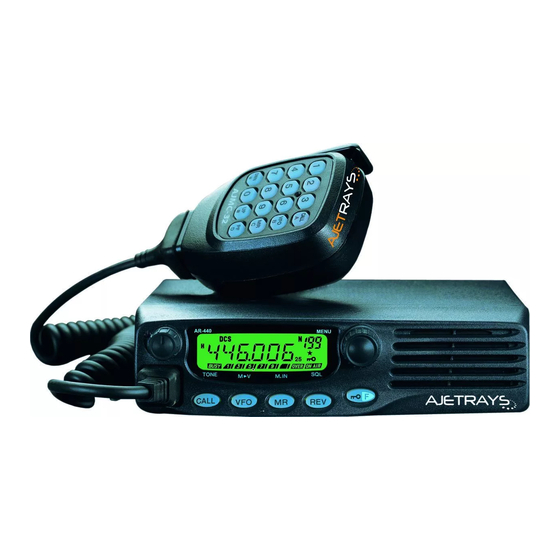
UHF FM TRANSCEIVER
AJETRAYS LLC 2010
CIRCUIT DESCRIPTION ............................ 2
SEMICONDUCTOR DATA ........................ 8
COMPONENTS DESCRIPTION ................ 9
PARTS LIST ............................................. 10
EXPLODED VIEW .................................... 17
PACKING ................................................. 18
RESETTING THE TRANSCEIVER ........... 19
ADJUSTMENT ........................................ 20
SERVICE MANUAL
Microphone
(T91-0641-05)
Knob (Volume)
Key top
(K29-9292-03)
(K29-9291-01)
CONTENTS
AR-440
Knob (Encoder)
(K29-9293-03)
TERMINAL FUNCTION ........................... 27
PC BOARD
DISPLAY UNIT (X54-3450-10) ............ 28
TX-RX UNIT (X57-686X-XX) ............... 30
SCHEMATIC DIAGRAM .......................... 34
BLOCK DIAGRAM ................................... 38
LEVEL DIAGRAM .................................... 40
SPECIFICATION ................... BACK COVER
Cabinet
(A01-2193-01)
Panel assy
(A62-1102-03)
Advertisement
Table of Contents

Related Manuals for Ajetrays AR-440

Summary of Contents for Ajetrays AR-440
-
Page 1: Table Of Contents
SERVICE MANUAL AR-440 UHF FM TRANSCEIVER AJETRAYS LLC 2010 Microphone (T91-0641-05) Cabinet (A01-2193-01) Knob (Volume) Key top Knob (Encoder) Panel assy (K29-9292-03) (K29-9291-01) (K29-9293-03) (A62-1102-03) CONTENTS CIRCUIT DESCRIPTION ......2 TERMINAL FUNCTION ......27 SEMICONDUCTOR DATA ......8 PC BOARD COMPONENTS DESCRIPTION .... -
Page 2: Circuit Description
AR-440 CIRCUIT DESCRIPTION ■ IF Amplifier Frequency Configuration The first IF signal is amplified by Q351, and then goes to The receiver utilizes double conversion. The first IF is IC301 (FM processing IC). The signal is heterodyned again 49.95MHz and the second IF is 450kHz. The first local oscil- with a second local oscillator signal within IC301 to create a lator signal is supplied from the PLL circuit. - Page 3 AR-440 CIRCUIT DESCRIPTION ■ Wide/Narrow Switching Circuit ■ Squelch Circuit The Wide port (pin 65) and Narrow port (pin 64) of the CPU The detection output from the FM IF IC (IC301) passes is used to switch between ceramic filters. When the Wide through a noise amplifier (Q301) to detect noise.
- Page 4 AR-440 CIRCUIT DESCRIPTION ■ Unlock Circuit Transmitter System During reception, the 8RC signal goes high, the 8TC signal ■ Outline goes low, and Q34 turns on. Q33 turns on and a voltage is The transmitter circuit produces and amplifies the desired applied to 8R.
- Page 5 ■ Key Matrix Circuit Control Circuit The AR-440 front panel has function keys. Each of them The CPU carries out the following tasks (See Fig. 10.): is connected to a cross point of a matrix of the KI1 to KI3 and 1) Controls the WIDE, NARROW, TX/RX outputs.
- Page 6 AR-440 CIRCUIT DESCRIPTION ■ Decode • CTCSS/DCS The signal (W/NO (EVOL2)) goes to DTMF IN (pin 95) of CPU (IC101). The CTCSS/DCS signal will pass through the low-pass filters in the CPU (IC101) and be decoded within the CPU (IC101). The DTMF signal will be decoded within the CPU (IC101).
- Page 7 AR-440 CIRCUIT DESCRIPTION ■ Transmission Signals PR1 is the 1200bps data communications reception out- put. It outputs the FM detection circuit output through an AF Transmission modulation signals enter from PKD of the filter (IC251). Output is controlled with the mute switch data terminal (CN2).
-
Page 8: Semiconductor Data
AR-440 SEMICONDUCTOR DATA Microprocessor : 30622MAA-B85GP (TX-RX Unit IC101) ■ Terminal Function Pin No. Name Function Pin No. Name Function TONE CTCSS/DCS/Clone output Common data DTMF DTMF/BEEP/1750Hz output Common clock PLLE PLL IC chip select DST1 Destination 1 57~59 DST2~DST4... -
Page 9: Components Description
AR-440 COMPONENTS DESCRIPTION Display Unit (X54-3450-10) Ref. No. Parts name Description Ref. No. Parts name Description Q351 Transistor IF amplifier LCD controller Q352 Mixer Transistor DC switch Q353 RF amplifier / LNA Transistor LCD backlit switch Q354 PC/TV switch Transistor... -
Page 10: Parts List
AR-440 PARTS LIST ✽ New Parts. indicates safety critical components. L : Scandinavia K : USA P : Canada Parts without Parts No. are not supplied. Y : PX (Far East, Hawaii) T : England E : Europe Les articles non mentionnes dans le Parts No. ne sont pas fournis. - Page 11 AR-440 PARTS LIST TX-RX UNIT (X57-686X-XX) Desti- Desti- Ref. No. Address Parts No. Description Ref. No. Address Parts No. Description parts nation parts nation C92-0795-05 CHIP-TAN 22UF 10WV C256 CK73GB1E183K CHIP C 0.018UF CK73GB1H103K CHIP C 0.010UF C257 CK73GB1C393K CHIP C 0.039UF...
- Page 12 AR-440 PARTS LIST TX-RX UNIT (X57-686X-XX) Desti- Desti- Ref. No. Address Parts No. Description Ref. No. Address Parts No. Description parts nation parts nation C371 CC73GCH1HR75B CHIP C 0.75PF C438 CC73GCH1H010B CHIP C 1.0PF C371 CC73GCH1H0R5B CHIP C 0.5PF C438,439...
- Page 13 AR-440 PARTS LIST TX-RX UNIT (X57-686X-XX) Desti- Desti- Ref. No. Address Parts No. Description Ref. No. Address Parts No. Description parts nation parts nation C555 CK73FB1C474K CHIP C 0.47UF L360 L34-4603-05 AIR-CORE COIL C556 C93-0599-05 CHIP C 470PF L360,361 L34-4604-05...
- Page 14 AR-440 PARTS LIST TX-RX UNIT (X57-686X-XX) Desti- Desti- Ref. No. Address Parts No. Description Ref. No. Address Parts No. Description parts nation parts nation RK73GB1J102J CHIP R 1.0K 1/16W R255,256 RK73GB1J562J CHIP R 5.6K 1/16W R91,92 RK73GB1J102J CHIP R 1.0K...
- Page 15 AR-440 PARTS LIST TX-RX UNIT (X57-686X-XX) Desti- Desti- Ref. No. Address Parts No. Description Ref. No. Address Parts No. Description parts nation parts nation R369 RK73GB1J151J CHIP R 1/16W R514 RK73FB2A470J CHIP R 1/10W R370 RK73GB1J473J CHIP R 1/16W R514...
- Page 16 AR-440 PARTS LIST TX-RX UNIT (X57-686X-XX) Desti- Desti- Ref. No. Address Parts No. Description Ref. No. Address Parts No. Description parts nation parts nation D606,607 MA742 DIODE D608 1SS355 DIODE IC31 KIA7808AF ANALOG IC IC32,33 NJM78L05UA BI-POLAR IC ✽ IC34...
-
Page 17: Exploded View
AR-440 EXPLODED VIEW A M2.6 x 8 : N67-2608-46 M2 x 10 BLK : N80-2010-45 M2.6 x 6 (Br-Tap) : N87-2606-46 D M2.6 x 14 (Br-Tap) : N87-2614-46 Display unit IC252 Cx12 Q504 TX-RX unit Sticker S/No. label Caution label... -
Page 18: Packing
AR-440 PACKING 5 Instruction manual (B62-1745-10) Pamphlet 33 Packing xture (H12-3112-05) 36 Protection bag (H25-2341-04) 36 Protection bag (H25-2341-04) 33 Packing xture (H12-3112-05) 50 AJMC-32 Microphone (T91-0641-05) 37 Item carton case (H52-2030-02) 46 Screw set (N99-0395-05) AJUA38 DC cord (E30-2111-15) -
Page 19: Resetting The Transceiver
AR-440 RESETTING THE TRANSCEIVER ■ VFO Reset Resetting the Tansceiver This resets the transceiver parameters excluding the If your transceiver seems to be malfunctioning, resetting DTMF Memory, the Memory channel contents, and the Call the microprocessor may solve the problem. The following 2 channel contents. -
Page 20: Adjustment
AR-440 ADJUSTMENT q Blinks in Adjustment Mode. Adjustment Mode w Adjustment item display In Adjustment Mode, the transceiver can adjusted using e Adjustment value display. Can be adjusted while it is its panel keys. “blinking”. Displayed as a hexadecimal number from 00 to FF. - Page 21 AR-440 ADJUSTMENT Adjustment Item Adjustment On the Note TX (MHz) RX (MHz) TX (MHz) RX (MHz) Signalling Frequency Point Display Frequency Tune Center 415.10 415.05 460.10 460.05 TX High Power “H” icon appear 400.10 400.05 440.10 440.05 Low’ 407.60 407.55 450.10...
- Page 22 AR-440 ADJUSTMENT Test Equipment Required for Alignment Test Equipment Major Specifications 1. Standard Signal Generator Frequency Range 400 to 520MHz (SSG) Modulation Frequency modulation and external modulation Output –127dBm/0.1µV to greater than –7dBm/100mV 2. Power Meter Input Impedance 50Ω Operation Frequency...
- Page 23 AR-440 ADJUSTMENT ■ Notes Adjustment Location • EEPROM ■ Adjustment Points The tuning data (Deviation, Squelch, etc.) for the EEP- ROM, is stored in memory. When parts are changed, re- adjust the transceiver. TX-RX unit Component side F501 • AF PA IC (IC252) How to mounting the IC252.
- Page 24 AR-440 ADJUSTMENT PCB Section Measurement Adjustment Specifications/ Item Condition Remarks Test equipment Terminal Parts Method 1. Setting 1) Power supply voltage DC Power supply terminal : 13.8V ± 0.2V 2. VCO lock 1) CH : TX high Digital voltmeter TC402 5.5V...
- Page 25 AR-440 ADJUSTMENT Measurement Adjustment Specifications/ Item Condition Test equipment Terminal Parts Method Remarks Encoder ± 4.0kHz (Wide) ± 100Hz (Wide) 6. MAX 1) CH : TX low (Wide) Modulation analyzer ANT ± 2.0kHz (Narrow) ± 50Hz (Narrow) deviation CH : TX center (Wide/Narrow)
- Page 26 AR-440 ADJUSTMENT Measurement Adjustment Specifications/ Item Condition Test equipment Terminal Parts Method Remarks 2. Squelch 1) CH : RX low (Wide) Encoder Adjust to open the squelch tight CH : RX center (Wide/Narrow) Oscilloscope EXT. SP knob CH : RX high (Wide) AF V.M...
-
Page 27: Terminal Function
AR-440 TERMINAL FUNCTION TX-RX UNIT (X57-686X-XX) CN No. Pin No. Name Function CN No. Pin No. Name Function ENC A Encoder A INT SP Internal speaker Microphone Key Check Ground ENC B Encoder B MIC KEY Microphone Key Data Out from LCD... - Page 28 AR-440 PC BOARD DISPLAY UNIT (X54-3450-10) Component side view (J72-0905-09) POWER/VOL HOOK MIC JACK CALL DISPLAY UNIT (X54-3450-10) Foil side view (J72-0905-09) HOOK...
- Page 29 AR-440 PC BOARD DISPLAY UNIT (X54-3450-10) Component side view (J72-0905-09) Ref. No. Address ENCODER FUNCTION Component side Layer 1 Layer 2 J72-0905-09 Foil side DISPLAY UNIT (X54-3450-10) Foil side view (J72-0905-09) Ref. No. Address ENCA ENCB MIC KEY POWER Component side...
- Page 30 AR-440 PC BOARD DISPLAY UNIT (X54-3450-10) Component side view (J72-0905-09) DISPLAY UNIT (X54-3450-10) Component side view (J72-0905-09) Ref. No. Address POWER/VOL ENCODER HOOK MIC JACK FUNCTION Component side CALL Layer 1 Layer 2 J72-0905-09 Foil side DISPLAY UNIT (X54-3450-10) Foil side view (J72-0905-09) DISPLAY UNIT (X54-3450-10) Foil side view (J72-0905-09) Ref.
- Page 31 AR-440 PC BOARD TX-RX UNIT (X57-686X-XX) 3-00 : C 3-01 : C2 Component side view (J72-0907-09) EXT. SP C536 C535 C538 C539 L507 C541 Q503 C543 C528 R536 R535 C534 R534 C527 IC 5 R526 R521 R524 R272 D251 C272...
- Page 32 AR-440 PC BOARD TX-RX UNIT (X57-686X-XX) 3-00 : C 3-01 : C2 Component side view (J72-0907-09) Ref. No. Address IC33 IC161 IC201 IC202 C574 IC203 C611 C575 IC204 C576 IC205 IC252 C555 IC401 C556 C610 IC501 Q201 Q252 Q253 C605...
- Page 33 AR-440 AR-440 PC BOARD PC BOARD TX-RX UNIT (X57-686X-XX) 3-00 : C 3-01 : C2 TX-RX UNIT (X57-686X-XX) 3-00 : C 3-01 : C2 Component side view (J72-0907-09) Component side view (J72-0907-09) Ref. No. Address EXT. SP IC33 IC161 IC201...
- Page 34 AR-440 PC BOARD TX-RX UNIT (X57-686X-XX) 3-00 : C 3-01 : C2 Foil side view (J72-0907-09) R800 L604 L603 C608 C607 D607 C604 C603 D606 D604 D603 D605 C601 L509 C572 C571 L361 C573 C385 D354 C387 D355 L359 R520...
- Page 35 AR-440 PC BOARD TX-RX UNIT (X57-686X-XX) 3-00 : C 3-01 : C2 Foil side view (J72-0907-09) Ref. No. Address IC31 IC32 IC34 IC35 IC66 IC101 IC251 IC301 Q251 Q301 Q352 Q353 Q404 Q405 Q406 Q407 Q408 Q410 Q411 Q440 Q500...
- Page 36 AR-440 AR-440 PC BOARD PC BOARD TX-RX UNIT (X57-686X-XX) 3-00 : C 3-01 : C2 TX-RX UNIT (X57-686X-XX) 3-00 : C 3-01 : C2 Foil side view (J72-0907-09) Foil side view (J72-0907-09) Ref. No. Address IC31 IC32 IC34 IC35 IC66...
-
Page 37: Schematic Diagram
AR-440 SCHEMATIC DIAGRAM TX-RX UNIT (X57-6863-XX) R414 Q402,403 RX VCO BUFFER AMP CHARGE PUMP C430 R:0.75V D403,404 Q410 D402 R410 RX VCO R:5.84V R:0.98V 2SC5108(Y) Q405 Q402 R:5.6V L406 C426 L408 HZU5ALL R418 R419 R421 L405 D404 2SK508NV(K52) C432 2SA1832(GR) - Page 38 AR-440 SCHEMATIC DIAGRAM TX-RX UNIT (X57-6863-XX R522 RF AMP/ PREDRIVE AMP RF SWITCH T:7.32V RF SWITCH Q501 Q500 RF AMP R:4.86V D409 2SC3356(R24) T:5.26V 2SC5110(O) T:7.1V T:0.17V T:7.15V T:1.6V R:7.03V T:4.5V DAN235E Q411 C502 C509 L504 C516 L505 C523 R525 C526 R:1.7V...
- Page 39 AR-440 SCHEMATIC DIAGRAM TX-RX UNIT (X57-6863-XX R800 F501 R:13.8V T:13.45V ANT SW RF AMP/ D601 DRIVE AMP 2 MA4PH633 Q503 C620 RF AMP/ PD55003TR FINAL AMP ANT SW Q504 D602 C541 C602 L603 L507 RD60HUF1-01 C570 MA4PH633 L602 1.5T 1.5T 470p T:0.8V...
- Page 40 AR-440 SCHEMATIC DIAGRAM DISPLAY UNIT (X54-3450-10) LCD (B38-0885-05) CALL MHz & MENU ADJUASTMENT W02-3665-05 Func ENCODER 0.1u 1SS355 SEG27 SEG26 MBL(Key A) SEG25 4.96V SEG24 ON/OFF & VOLUME SEG23 ADJUASTMENT HOOK SEG22 4.94V SEG20 LCD CONTROLLER R31-0646-05 SEG20 PT6554LQ VDD1...
- Page 41 AR-440 AR-440 SCHEMATIC DIAGRAM SCHEMATIC DIAGRAM TX-RX UNIT (X57-6863-XX) DISPLAY UNIT (X54-3450-10) R800 R522 F501 LCD (B38-0885-05) R414 RF AMP/ R:13.8V Q402,403 RF SWITCH PREDRIVE AMP T:13.45V CHARGE PUMP RX VCO BUFFER AMP RF SWITCH T:7.32V R:0.75V Q501 D403,404 C430...
-
Page 42: Block Diagram
AR-440 BLOCK DIAGRAM DISPLAY UNIT (X54-3450-10) TX-RX UNIT (X57-686X-XX) Q404 2SC4649(N,P) MIC KEY 2SK50 R31-0649-05 Q402 VIARIABLE RESISTOR IC401 POWER PTT(TXD) CHARGE 2SA1832(GR) MB15A02 PUMP PLLE HOOK(RXD) LOOP Q407 PLL IC CM(MIC KEY2) FILTER 2SJ347 16.8MHz CHARGE Q403 CALL PUMP 16.8MHz... - Page 43 AR-440 BLOCK DIAGRAM D601,602 Q501 MA4PH633 2SC3356 Q502 Q503 Q504 Q500 Q410 Q411 Q405 D603,604 (R24) 2SK2596 PD55008 RD60HUF1 2SC5110(O) 2SC5108(Y) 2SC5108(Y) 2SK508NV(K52) XB15A709 DRIVE DRIVE FINAL DRIVE BUFF ANT SW AMP1 AMP2 Q408 D409 Q407 KRX102U DAN235E 2SJ347 POW.
-
Page 44: Level Diagram
AR-440 LEVEL DIAGRAM Receiver Section Center Frequency 49.95MHz 450kHz W : –85.0dBm N : –80.5dBm W : –122.0dBm W : –119.0dBm W : –105.5dBm W : –105.0dBm W : –118.5dBm W : –103.0dBm /CF2 N : –121.5dBm N : –118.5dBm N : –104.5dBm... - Page 45 AR-440 LEVEL DIAGRAM 450kHz Audio Frequency W : –93.0dBm N : –91.0dBm /CF2 0.33Vrms 0.32Vrms 0.27Vrms 0.30Vrms 0.31Vrms 10mVrms 0.50Vrms 0.64Vrms IC301 IC251 IC251 IC251 IC251 IC161 IC252 Q251 vel meter. 12dB SINAD.) To make measurements in the AF section, connect the AC level meter.
-
Page 46: Specification
AR-440 SPECIFICATIONS GENERAL Frequency Range RX/TX ................400~480MHz ..................C : 400~430MHz C2 : 440~480MHz RX ..................C : 400~430MHz C2 : 440~480MHz Mode ..................F3E (FM) Antenna Impedance ............50Ω Usable Temperature Range ..........–20°C~+60°C (–4°F~+140°F) Power Supply ............... 13.8V DC± 15% (11.7~15.8V) Grounding Method ..............
Need help?
Do you have a question about the AR-440 and is the answer not in the manual?
Questions and answers