
Subscribe to Our Youtube Channel
Related Manuals for Pego ECP APE 03


Summary of Contents for Pego ECP APE 03
- Page 1 ECP APE 03 manual * Alle Angaben sind ohne Gewähr, Änderungen bleiben V-2201-001 CI GmbH CONTROL INSTRUMENTS vorbehalten.
-
Page 2: Table Of Contents
6CIAPE03 - ENG - ENGLISH CONTENTS INTRODUCTION CHAP. 1 Page 2 MAN IN COLD ROOM ALARM KIT COMPONENTS Page 2 PRODUCT IDENTIFICATION CODES Page 2 TECHNICAL CHARACTERISTICS Page 3 DIMENSIONS OF ALARM CONTROL UNIT Page 3 DIMENSIONS OF EMERGENCY PUSHBUTTON UNIT Page 3 IDENTIFICATION DATA Page 4... -
Page 3: Man In Cold Room Alarm Kit Components
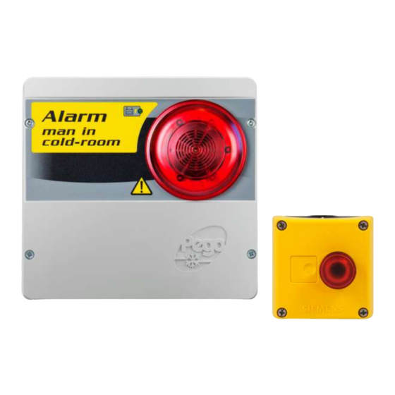
CHAP. 1 - Introduction 6CIAPE03 - ENG - CHAPTER 1: INTRODUCTION MAN IN COLD ROOM ALARM KIT COMPONENTS THE MAN IN COLD ROOM ALARM KIT consists of: - Visual/acoustic alarm control unit complete with buffer battery. - N° 3 seals, to be inserted between fixing screw and box backing. - Emergency cold room light switch. -
Page 4: Dimensions Of Alarm Control Unit
CHAP. 1 - Introduction 6CIAPE03 - ENG - DIMENSIONS OF ALARM CONTROL UNIT DIMENSIONS OF EMERGENCY PUSHBUTTON UNIT IDENTIFICATION DATA The unit described in this manual has, on its side, an ID plate showing all the relevant identification data: • Name of Manufacturer •... -
Page 5: Description Of System
CHAP. 1 - Introduction 6CIAPE03 - ENG - DESCRIPTION OF SYSTEM The purpose of this safety system is to allow a person trapped inside the cold room to activate an acoustic/luminous alarm located outside the room and so request help. The system has been designed to function even in the event of a temporary mains power failure: in this event the system is powered by a buffer battery housed in the external unit. -
Page 6: Installing The Out-Of-Room Alarm Control Unit
CHAP. 2 - Installation 6CIAPE03 - ENG - CHAPTER 2: INSTALLATION INSTALLING THE OUT-OF-ROOM ALARM CONTROL UNIT Undo the 4 closure screws on the front panel. Use the three existing holes to fix the box back panel to the wall: use three screws of a length suitable for the thickness of the wall to which the panel will be attached. -
Page 7: Installing The In-Room Emergency Pushbutton Unit
CHAP. 2 - Installation 6CIAPE03 - ENG - INSTALLING THE IN-ROOM EMERGENCY PUSHBUTTON 1. The in-room pushbutton must be positioned so that it is always visible and easily reachable. 2. Undo the two closure screws on the front of the pushbutton panel. 3. -
Page 8: Exploded Diagram
CHAP. 2 - Installation 6CIAPE03 - ENG - EXPLODED DIAGRAM DESCRIPTION BOX BACKING IN ABS BOARD ATTACHMENT SCREWS BUFFER BATTERY SUPPORT FIXING SCREWS BOARD BUFFER BATTERY SUPPORT METAL SHEETING FRONTAL SECTION IN ABS ACOUSTIC/VISUAL ALARM BOX CLOSURE SCREWS ACOUSTIC/VISUAL ALARM ATTACHMENT SCREWS BUFFER BATTERY USE AND MAINTENANCE MANUAL Pag.7... -
Page 9: Electrical Connections
CHAP. 2 - Installation 6CIAPE03 - ENG - ELECTRICAL CONNECTIONS Warning : The positive pole of the battery (Fastom with red wire) is initially disconnected to maintain the charge during product storage. Once the in-room keypad connections have been made it is, therefore, necessary to connect this fastom to the connector marked (1) on the upper left side of the board as also indicated on the wiring diagram. -
Page 10: Warranty Terms
Modifications/improper work can also cause malfunctions, irreparable damage, serious injury or put persons/objects in danger. PEGO S.r.l. cannot be held liable for possible errors or inaccuracies written in this manual as a result of printing or transcription errors. PEGO S.r.l. reserves the right to modify its products as it deems necessary without altering its main characteristics. -
Page 11: Ec Declaration Of Conformity
6CIAPE03 - ENG - APPENDICES EC DECLARATION OF CONFORMITY COSTRUTTORE: MANUFACTURER: PEGO S.r.l. Via Piacentina, 6/b 45030 Occhiobello (RO) – Italy – Tel. (+39) 0425 762906 Fax. (+39) 0425 762905 DENOMINAZIONE DEL PRODOTTO: NAME OF THE PRODUCT: 6CIAPE03 MOD.: IL PRODOTTO E’ CONFORME ALLE SEGUENTI DIRETTIVE CE:... - Page 12 CI GmbH CONTROL INSTRUMENTS Baumschulenweg 10 - 70736 Fellbach - DE www.ci-gmbh.com info@ci-gmbh.com + 49 711 65883-0...
Need help?
Do you have a question about the ECP APE 03 and is the answer not in the manual?
Questions and answers