Table of Contents
Advertisement
Quick Links
ELAN DIGITAL SYSTEMS LTD.
website:
Important Notice: Please refer to Safety Data 4.4.1, before using this instrument
ISSUE
PAGES
1
30
2
30
3
31
4
31
5
39
6
43
7
44
8
34
Elan Digital Systems Ltd.
LITTLE PARK FARM ROAD,
SEGENSWORTH WEST,
FAREHAM,
HANTS. PO15 5SJ.
TEL: (44) (0)1489 579799
FAX: (44) (0)1489 577516
e-mail:
sales@elandigitalsystems.com
http://www.elandigitalsystems.com
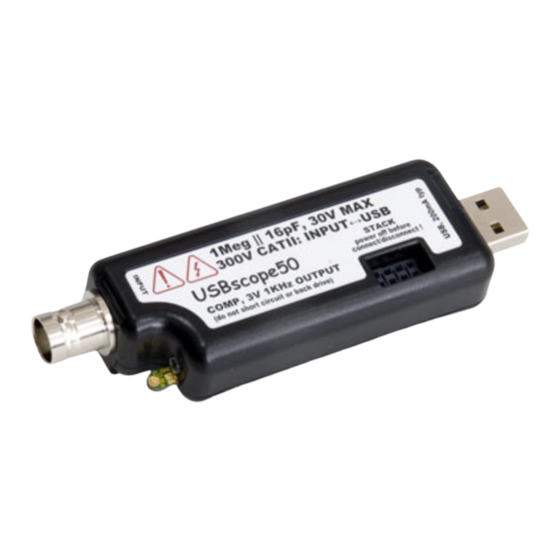
USBscope50
USERS GUIDE
ES370
All Trademarks are duly acknowledged.
The USBscope50 is Patent Pending.
REVISION HISTORY
DATE
04.07.2005
08.07.2005
15.07.2005
20.07.2005
27.09.2005
06.10.2005
11.01.2006
22.04.2009
NOTES
FIRST ISSUE
Various additional info & spec amendments
Add support for Win98 & DBCS Language's in
2K/XP
Various additional info & amendments
General update. Explain trigger modes, Math,
FFTs etc
Add clipboard feature and MIS mode
Add offset null feature
User Guide for New Java Software
1
USBscope50 USER'S GUIDE Iss8
Advertisement
Table of Contents

Summary of Contents for ELAN DIGITAL SYSTEMS USBscope50
- Page 1 USBscope50 USERS GUIDE ES370 Important Notice: Please refer to Safety Data 4.4.1, before using this instrument All Trademarks are duly acknowledged. The USBscope50 is Patent Pending. REVISION HISTORY ISSUE PAGES DATE NOTES 04.07.2005 FIRST ISSUE 08.07.2005 Various additional info &...
-
Page 2: Table Of Contents
2.4.1 Offset Nulling....................16 2.5 Probe Compensation..................16 2.6 Acquisition Modes....................20 2.6.1 Single Shot....................20 2.6.2 Random Interleaved Sampling..............21 2.7 Trigger Modes....................22 2.7.1 USBscope50 continuous run in Free Mode..........23 2.7.2 Normal Triggering..................23 2.8 Trigger Position....................23 2.9 Trigger Threshold....................24 2.10 Data manipulation..................24 2.10.1 Save Graph....................24 2.10.2 Export Graph Data..................24... - Page 3 3.2 Linux Ubuntu....................29 3.3 Troubleshooting....................30 4 HARDWARE SPECIFICATION..............31 4.1 Power Requirements..................31 4.2 Mechanical......................31 4.3 Environmental....................31 4.4 Performance......................32 4.4.1 Safety Data and Maximum Ratings.............32 4.4.2 Static Performance..................33 4.4.3 Dynamic Performance.................34 4.4.4 Miscellaneous....................34 4.4.5 Software.......................34 Elan Digital Systems Ltd. USBscope50 USER’S GUIDE Iss8...
- Page 4 Elan assumes no liability for any direct or indirect losses arising from use of the supplied code. Copyright © 2009 Elan Digital Systems Ltd. Federal Communications Commission (FCC) Statement This equipment has been tested and found to comply with the limits for a Class A digital device, pursuant to Part 15 of the FCC Rules.
-
Page 5: Overview
USB connection) 300V Cat II isolation between BNC ground and USB ground • This means that there is no DC path through the USBscope50 from your scope ground clip to the PC’s ground • 50MSample/sec single shot sample rate 1GSample/sec equivalent sample rate •... -
Page 6: About The Usbscope50
The CAT rating refers to how large a transient over-voltage may be when connected to the circuit in question. The USBscope50 is designed to handle a certain transient over-voltage between the BNC and the USB host i.e. across the internal isolation circuits. The CAT II UL rating defines a more severe environment than CAT I and hence larger transients are possible. -
Page 7: Usbscope50 Architecture
2.2 USBscope50 Architecture The figure below shows a simplified diagram of the USBscope50. STACK AC/DC CONN CONTROLLER Trigger CONTROLLER COMP DATA ATTENUATOR 8-BIT ADC 1Meg ISOLATION BARRIER Figure 2.2-1 USBscope50 Architecture Diagram Elan Digital Systems Ltd. USBscope50 USER’S GUIDE Iss8... -
Page 8: Using More Than One Usbscope50
2.3.1.1 Assembling The Stack To stack the USBscope50 devices, first be sure that none of them are connected to a USB port. Before you begin, put the short lead connectors to one side…you’ll only need one of these. - Page 9 Similarly, if you plan to use only one scope, make sure there is no stack connector fitted or the shorter connector type is fitted. This is a safety critical point so please note it carefully. Now you can assemble the stack. Elan Digital Systems Ltd. USBscope50 USER’S GUIDE Iss8...
-
Page 10: Disassembling The Stack
Start with the top scope in the stack. Grasp the stack in one hand and with the other hand’s thumb and forefinger, pinch between the interface between the top two scopes, near the back “P” clip (USB Elan Digital Systems Ltd. USBscope50 USER’S GUIDE Iss8... -
Page 11: Usb Connections For Stacked Configurations
2.3.1.4 Software For Stacked Configurations When you run USBscope50, it will automatically detect the scopes connected via USB and will also check to see if the scopes are electrically connected together via the stack. It will then initialise all connected scopes, one at a time. -
Page 12: Stacking Do's And Don'ts
• Don’t short circuit any of the stack connector pins, or bend the pins or use excessive force trying to mate the connectors • Don’t probe or drive any of the stack connector signals • Avoid touching the stack connector pins/signals during stacking Elan Digital Systems Ltd. USBscope50 USER’S GUIDE Iss8... -
Page 13: Non-Stacked (Mis) Mode
They can of course still be snapped together, but remember NOT to fit any of the stacking connectors so that the scopes remain electrically independent of each other. Elan Digital Systems Ltd. USBscope50 USER’S GUIDE Iss8... -
Page 14: Software For Non-Stacked Configurations
For example, if you want to run 2 scopes in MIS mode plug in one USBscope50, and then run USBscope50 Software. Confirm that channel 1 is detected and running. Insert the second USBscope50 in the USB port and run another instance of the Java software by double clicking on the Desktop icon. -
Page 15: Input Ranges
Settings → Channel Colours and in Settings → Chart Settings. 2.4 Input Ranges The USBscope50 supports 3 settings on its input attenuator. These are then adjusted in the software to expand the range which user can adjust by pressing the arrow keys. -
Page 16: Offset Nulling
DC up to 75MHz. 2.4.1 Offset Nulling The input stages of the USBscope50 will naturally tend to cause a small DC offset error in any readings, and this will change from range to range and from scope to scope. In order to null this offset out, the software is able to subtract a DC level from all its readings and its plots, that will help to remove this error. - Page 17 Later models have a dual pad compensation point that includes a GND pad Some very high frequency low capacitance probes may not be suitable for use with the USBscope50 Elan Digital Systems Ltd. USBscope50 USER’S GUIDE Iss8...
- Page 18 Be careful not to short-circuit the GND pad to the COMP output with the ground clip. A momentary short circuit is not harmful but leaving a sustained short may damage the scope’s output Elan Digital Systems Ltd. USBscope50 USER’S GUIDE Iss8...
- Page 19 This overshoot may be very narrow and seem to come and go…this is normal. Better quality scope probes have better transient response and so have smaller overshoot. Elan Digital Systems Ltd. USBscope50 USER’S GUIDE Iss8...
-
Page 20: Acquisition Modes
2.6 Acquisition Modes The USBscope50 can acquire waveforms in two different ways. Single shot and continuous run mode 2.6.1 Single Shot In this mode, the ADC is clocked at up to 50MegaSamples/sec. Each sample is placed into the buffer and then the buffer is painted on the screen. -
Page 21: Random Interleaved Sampling
This mode is a little more complex and is suited only to observing certain types of waveform. The USBscope50 includes special circuitry that allows it to trigger off the input waveform and also to be able to measure the time between the trigger instant and the first ADC sample that is taken. -
Page 22: Trigger Modes
This is normal. 2.7 Trigger Modes The USBscope50 can use two main types of triggering. These modes are used when the “Run” button or the “Trigger Single” button has been pressed causing the scope to enter the run state. -
Page 23: Usbscope50 Continuous Run In Free Mode
2.7.1 USBscope50 continuous run in Free Mode In this mode the acquisition begins just after the software has set up the scope. The scope will effectively free run, with no attempt to lock to the input waveform and displaying all the the graph as soon as data is available. -
Page 24: Trigger Threshold
USBscope50 Software application. 2.10 Data manipulation 2.10.1 Save Graph With USBscope50 Java software you can save graph in one of the following formats: jpg, pnp or pdf. Please select menu option File → Save Graph. 2.10.2 Export Graph Data USBscope50 Software displays 3000 data points on the graph. -
Page 25: Example Data File
There are 3000 sets of numbers. Document contains the header that defines the acquisition mode used. //USBscope50 Software loaded this file with the 3000 graph points. //Use software option Edit -> Import to recreate the graph. DATA ON CHANNEL : 2... -
Page 26: Import Graph Data
All lines beginning with “//” in the text file will be ignored by software. Use this if you wish to write comments or not include certain data points on the graph. Elan Digital Systems Ltd. USBscope50 USER’S GUIDE Iss8... -
Page 27: Software Development Kit (Sdk) For Usbscope50
2.12 Software Development Kit (SDK) for USBscope50 While running the USBscope50 Java application try selecting Help option from the software menu or pressing F1 key. You should get some additional help pages on how to use the software and also detailed information on SDK for USBscope50. -
Page 28: Software Installation
PC. After running the setup program: Insert the USBscope50 into a free USB socket, or into a USB hub port. A USB extension cable can be used if needed. During installation hardware device is detected: “USBscope50”. -
Page 29: Linux Ubuntu
Once the hardware has installed, there is no need to make any settings for the allocated COM port…the software takes care of all this at run time Start the USBscope50 software and you will see the following display: To find out what the various buttons and knobs do, simply hover over them for a brief explanation. -
Page 30: Troubleshooting
Copy USBscope50_Software.jar and lib folder in the same location. To run this Java Application you need Java Runtime Environment (JRE). USBscope50 Software is not bound to a JRE version, but we would advise customers to keep JRE up to date. -
Page 31: Hardware Specification
10mins for rated accuracy Storage Temperature: -40°C to +80°C Ambient Operating Location: Indoor or under-cover use only Operational Category: Cat II Pollution Degree: From BNC end to USB end Not including “P” clips on base Elan Digital Systems Ltd. USBscope50 USER’S GUIDE Iss8... -
Page 32: Performance
In such a case do not connect anything to the USBscope50 to avoid a hazard. The USBscope50 will have to be repaired or replaced in such a situation. -
Page 33: Static Performance
This level will saturate the scope input, and is the maximum that can be applied without causing damage to the scope. It applies regardless of the input attenuator or coupling setting. Single shot mode only Elan Digital Systems Ltd. USBscope50 USER’S GUIDE Iss8... -
Page 34: Dynamic Performance
The circuit involved with triggering causes the maximum input frequency that can trigger the scope to be lower than the scopes measurement channel bandwidth. Works in USB 1.1 or USB 2.0 hosts using the 12MBits/sec full speed mode Elan Digital Systems Ltd. USBscope50 USER’S GUIDE Iss8...
Need help?
Do you have a question about the USBscope50 and is the answer not in the manual?
Questions and answers