Table of Contents
Advertisement
Quick Links
Advertisement
Table of Contents
Troubleshooting

Subscribe to Our Youtube Channel
Summary of Contents for Microplex SOLID F166 HD
- Page 1 Engine Information...
-
Page 2: Copyright And Trademark Notices
© Copyright 2006-2013 MICROPLEX Printware Corp.. All Rights Reserved. Reproduction, adaptation, or translation in any forms or by any means without the prior written permission of MICROPLEX Printware Corp.. is prohibited. The content in this manual document is subject to change without prior notice. -
Page 3: Documentation Conventions
SOLID F166 HD User Manual Documentation Conventions This document uses the following conventions. 【Note】 Notes contain important information. Caution messages appear before procedures, which, if not CAUTION observed, could result in damage to parts and consumables. Warning messages alert the reader to a specific procedure or... -
Page 4: Regulation Statements And Notices
SOLID F166 HD User Manual Regulation Statements and Notices This product is not for use at visual display work places. FCC Statement and Notice This device complies with part 15 of the FCC rules. Operation is subject to the following two conditions: (1) This device may not cause harmful interference, and (2) this device must accept any interference received, including interference that may cause undesired operation. - Page 5 SOLID F166 HD User Manual Declaration of Conformity for EU Countries We, MICROPLEX Printware Corp.. do hereby declare that this KPOWR printer conforms to the requirements of Directive 2006/95/EC and 2004/108/EC. Compliant with Regulatory Certification...
-
Page 6: Safety Information
SOLID F166 HD User Manual Safety Information Thanks for using MICROPLEX product. MICROPLEX Printware Corp.. is an ISO 9001 certified manufacturer. It’s our responsibility to inform users about the following safety information: Safety Instructions 1. Installation: After moving the printer, examine the power cord and confirm good connection of each connector before turn on the printer. - Page 7 4. Consumables: Please use MICROPLEX’s consumables to ensure the engine function and life as well as the print quality.
- Page 8 Disclaimers Please follow all warnings, precautions, and maintenance as recommended in this manual to maximize the life of this MICROPLEX printer. If users do not employ correct ways and steps to store and operate MICROPLEX printers, and/or use non-MICROPLEX parts and consumables, MICROPLEX Printware Corp..
-
Page 9: Warning Label Explanations
SOLID F166 HD User Manual Warning Label Explanations This printer contains the following warning labels. Please follow all warnings and precautions to ensure your safety. Moving parts. Do not touch while printing. Keep hands clear while printing. Hot surface. Do not touch. - Page 10 SOLID F166 HD User Manual CAUTION: Do not touch fuser unit cover glass. The fuser unit cover glass becomes very hot after operation. Contact may cause burn. Do not touch. Allow the fuser unit cover glass to fully cool before servicing.
-
Page 11: Table Of Contents
SOLID F166 HD User Manual CONTENTS Copyright and Trademark Notices..............i Documentation Conventions................ii Regulation Statements and Notices..............iii Safety Information................... v Warning Label Explanations................viii Chapter 1 Overview Features..................1-1 Components.................1-2 (1) External View..............1-2 (a) Inside the Front Cover............1-4 (b) Inside the Rear Cover.............1-5 (2) Principles of Laser Printers..........…1-6... - Page 12 SOLID F166 HD User Manual (3) Paper Orient Indicators............3-2 (4) Off-Line Functions..............3-2 Power on..................3-3 Paper Handling................3-4 (1) Paper Setting..............…... 3-4 (2) Paper Removal..............3-6 Chapter 4 Maintenance Periodic Maintenance by Operators..........4-1 Cleaning..................4-3 (1) Tractor Unit..............…... 4-3 (2) Transport Unit..............…...
- Page 13 SOLID F166 HD User Manual Chapter 5 Troubleshooting Paper Jam..................5-1 Error Code.................. 5-4 Error Code Descriptions and Countermeasures......5-6 Developer and Toner Troubleshooting........5-11 Image Quality Troubleshooting...........5-12...
-
Page 14: Chapter 1 Overview
SOLID F166 HD User Manual Chapter 1 Overview... -
Page 15: Features
SOLID F166 HD User Manual 1.1 Features SOLID F166 HDlaser printer is a high-quality page printer, which is appropriate for text and image printing. ( 1 ) High Speed - SOLID F166 HDprinter has an excellent performance of high speed printing. Printing text, image and graphic is certainly at full speed. -
Page 16: Components
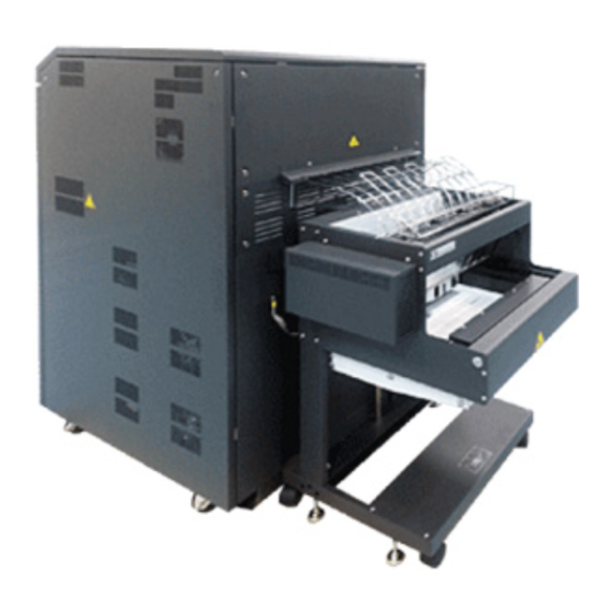
SOLID F166 HD User Manual 1.2 Components (1)External View SOLID F166 Top cover Left side cover Front cover (upper) Rear cover Right side cover Right side cover (rear) (front) Power switch Stacker Front cover (lower) Circuit breaker Lever foot Caster... - Page 17 SOLID F166 HD User Manual SOLID F166 Rear cover Left side cover (upper) Paper outlet cover plate Left side cover (lower) Stacker Fig. 1-2...
-
Page 18: (A) Inside The Front Cover
SOLID F166 HD User Manual (a) Inside the Front Cover Cleaning unit Fuser unit Erase lamp unit Carbon filter Main charger Transport unit Developing unit Dust filter Toner cartridge Air filter OPC drum Waste toner box Flash power supply DC Power supply... -
Page 19: (B) Inside The Rear Cover
SOLID F166 HD User Manual (b) Inside the Rear Cover Drum surface potential sensor unit Drum motor unit Elevator motor unit Varistor PCB Developing motor unit Fuser exit blower Blower unit (Air filter) DCMTR DRV board Splitter Paper out Motor unit... -
Page 20: Principles Of Laser Printers
(3) Sensor System Description The sensor system of SOLID F166 HD Series is shown in the following figures. Fuser unit Developing unit... - Page 21 SOLID F166 HD User Manual Fig. 1-9_2 1. Paper Empty Sensor (PES) <Cross Sensor> 2. Paper Top Sensor (PTS) <Sensor PS-R50D> 3. Front Cover Sensor (FRT-COVER) 4. Drum Surface Potential Sensor (DSPS) 5. Lamp Thermistor Sensor 6. Paper Transport Position Sensor (PTPS) <Sensor PS-R50D>...
-
Page 22: Specifications
SOLID F166 HD User Manual 1.3 Specifications General Scope Print speed 3500 / 5500 lines/minute (6LPI) Print method Electrophotography process, LED array Resolution 300 × 300 DPI / 600 × 600 DPI Print width 17 inches max. Paper feed rate... - Page 23 SOLID F166 HD User Manual Paper Type Fanfold paper (standard) Page length 7 to 20 inches Page width 6 to 18 inches (Fanfold paper) (When the power stacker unit is used, paper length range is 7 to 14 inches). Weight...
-
Page 24: Chapter 2 Environment
SOLID F166 HD User Manual Chapter 2 Environment... -
Page 25: Printer
SOLID F166 HD User Manual 2.1 Printer (1) Installation space: The following figure exhibits the printer dimensions, and the required operation zone and maintenance zone. Stacker SOLID F166 △ Front inches) (Dimensions in Fig. 2-1 2- 1... -
Page 26: Connecting To A Host
SOLID F166 HD User Manual (2) Connecting to a Host Install the printer on a proper and safe location where the host and power source is accessible. Before connect or disconnect any cable, turn off the printer power and circuit breaker (see section 〝 3.2 Power on 〞... -
Page 27: Paper
SOLID F166 HD User Manual 2.2 Paper ( 1 ) Paper Specifications ( a ) Weight 60 ~ 204 g /㎡ ( b ) Size Length: 7 ~ 20 INCH Width: 6 ~ 18 INCH ( c ) Others Be aware of the print area of perforation. -
Page 28: Chapter 3 Operation
SOLID F166 HD User Manual Chapter 3 Operation 2- 2... -
Page 29: Operation Panel
SOLID F166 HD User Manual 3.1 Operation Panel Fig. 3-1 (1)Function Keys No error exists: Set the printer in the on-line or off-line state. ON LINE Error exists: Clear the error message. FORM LENGTH Set paper length. Manually feed paper by 1 / 12 INCH. -
Page 30: Status Indicators
SOLID F166 HD User Manual ( 2 ) Status Indicators READY (GREEN) Off: Printer is warming up. On: Printer is in the on-line state. Out: Printer is in the off-line state. Blinking: Data is in buffer when printer is ready. -
Page 31: Power On
SOLID F166 HD User Manual 3.2 Power on Turn on the circuit breaker firstly. Then turn on the power switch to start the printer. Power switch Circuit breaker (Turn it off when idle for a long period of time.) Fig. 3-3 After the power is on, the LCD screen on the operation panel displays 〝... -
Page 32: Paper Handling
SOLID F166 HD User Manual 3.3 Paper Handling (1)Paper Setting ( a ) Make sure the left tractor is set at the left end, and align the left side of the paper carton with the alignment mark. Tractors Fig. 3-4 Alignment mark Fig. - Page 33 SOLID F166 HD User Manual ( b ) Supply the fanfold paper between the paper empty sensor guide and the printer body. Make sure the perforation of the first page is consistent with the “PAPER ORIENT” setting. Open the paper holder covers on the tractors.
-
Page 34: Paper Removal
SOLID F166 HD User Manual ( 2 ) Paper Removal ( a ) Press the 〝 ON Line 〞 key on the operation panel to set the printer in the off-line state. The green light of the status indicator 〝 READY 〞 is out. -
Page 35: Chapter 4 Maintenance
SOLID F166 HD User Manual Chapter 4 Maintenance 3- 2... -
Page 36: Periodic Maintenance By Operators
SOLID F166 HD User Manual 4.1 Periodic Maintenance by Operators (Count by 8.5” size, B/W 4%) Time-Clean Item Tool (in pages) Brush Tractor unit Vacuum cleaner Vacuum cleaner Transport unit Dry cloth with alcohol Scraper Transport belt Dry cloth with alcohol... - Page 37 SOLID F166 HD User Manual 【Note】 1. Pack the consumables properly before storage. 2. Store the consumables in a cool dry dark place and protect them from being exposed to humidity, temperature extremes, or direct sunlight. Do not store the consumables for more than six months.
-
Page 38: Cleaning
SOLID F166 HD User Manual 4.2 Cleaning ( 1 ) Tractor Unit In order to clean the tractor unit, use a vacuum cleaner to clear the paper dust scattered around the tractor unit. Tractor unit Fig. 4-1 4- 3... -
Page 39: Transport Unit
SOLID F166 HD User Manual ( 2 ) Transport Unit ( a ) Open the front cover (upper). Press down the opening lever to open the waste toner box unit. Waste toner box unit Opening lever Fig. 4-2 ( b ) Incline the green lever of the transport unit to the left to lower the transport surface, then pull out the transport unit. - Page 40 SOLID F166 HD User Manual ( c ) Use a vacuum cleaner to clear the scattered paper dust or toner particles. Transport unit Green lever Fig. 4-4 ( d ) Use a piece of cloth with alcohol to remove the dirt on the transport surface and paper transport position sensor (PTPS).
- Page 41 SOLID F166 HD User Manual ( e ) Use a scraper to scrape off the dirt remained on the transport surface. Scraper Fig. 4-6 ( f ) After cleaning, insert the transport unit back as it was originally, and when the transport unit comes in contact with the inner end, raise the green lever to the right.
-
Page 42: Main Charger
SOLID F166 HD User Manual ( 3 ) Main Charger ( a ) Open the front cover (upper). Pull out the cleaning rod and then insert it back several times for cleaning the wire. Main charger Cleaning rod Fig. 4-8 (... - Page 43 SOLID F166 HD User Manual ( c ) Use the brush to wipe off the dust on the main charger. Fig. 4-10 ( d ) Push the plastic end of main charger to loosen the grid and detach the grid.
- Page 44 SOLID F166 HD User Manual ( e ) Use the wire cleaner (applied with alcohol) to clean the wire of the main charger. Fig. 4-12 ( f ) After cleaning, insert the plastic pin into the rectangle hole of the grid.
- Page 45 SOLID F166 HD User Manual ( g ) While pushing the plastic end of main charger, insert the metal pin into the rectangle hole of the other end of the grid. Grid Metal pin Fig. 4-14 ( h ) After cleaning, insert the main charger to its original location and tighten the thumbscrew.
-
Page 46: Pre-Charger
SOLID F166 HD User Manual ( 4 ) Pre-Charger ( a ) Open the front cover (upper). Press down the opening lever to open the waste toner box unit. Waste toner box unit Opening lever Fig. 4-15 ( b ) Loosen the thumbscrew and pull out the pre-charger. - Page 47 SOLID F166 HD User Manual ( d ) Use the wire cleaner (applied with alcohol) to clean the wire of the pre- charger. Pre-charger Fig. 4-17 ( e ) After cleaning, insert the pre-charger to its original location and tighten the thumbscrew. Close the waste toner box unit.
-
Page 48: Transfer Charger
SOLID F166 HD User Manual ( 5 ) Transfer Charger ( a ) Open the front cover (upper). Press down the opening lever to open the waste toner box unit. Waste toner box unit Opening lever Fig. 4-18 ( b ) Pull out the cleaning rod and then insert it back several times for cleaning the wire. - Page 49 SOLID F166 HD User Manual ( c ) Confirm that the transfer charger is at the “down” position. If the transfer charger is not at the “down” position, use a slotted screwdriver to turn the transfer elevator drive shaft counterclockwise to lower the transfer charger to the “down”...
- Page 50 SOLID F166 HD User Manual ( e ) Use the brush to wipe off the dust on the transfer charger. Fig. 4-22 ( f ) After cleaning, insert the transport unit back as it was originally, and when the transport unit comes in contact with the inner end, raise the green lever to the right.
-
Page 51: Fuser Cover Glass
SOLID F166 HD User Manual (6)Fuser Cover Glass CAUTION a) Do not handle the fuser unit (Pre-heat lamp & Xenon lamp) until it has fully cooled due to the unit becomes very hot after operation. The fuser unit is not available to be pulled out when it’s not fully cooled. - Page 52 SOLID F166 HD User Manual 3. Use both hands to hold the handling bars, and detach the fuser unit from the main body. Handing bars Fig. 4-26 4. Use dry cloth with alcohol to clean the fuser cover glass. Cover glass Fig.
-
Page 53: Paper Empty Sensor Area
SOLID F166 HD User Manual ( 7 ) Paper Empty Sensor Area Use a brush to clean the paper empty sensor area. Fig. 4-29 Fig. 4-30 4- 18... -
Page 54: Opc Drum Shaft & Flange
SOLID F166 HD User Manual ( 8 ) OPC Drum Shaft & Flange ( a ) Open the front cover (upper). Then turn the lever of the developing unit by 120° to the right to detach the developing unit. Lever Fig. - Page 55 SOLID F166 HD User Manual ( c ) Take out the OPC drum (see “4.3 Replacement: (6) OPC Drum”). ( d ) Clean the drum shaft with dry cloth. Drum shaft Fig. 4-33 ( e ) Use dry cloth with alcohol to clean the drum flanges on both sides.
- Page 56 SOLID F166 HD User Manual ( g ) Make sure to place the handling bar towards left, and then insert the developing unit. Handling bar Fig. 4-35 ( h ) Align the pinhole on the unit with the positioning pin on the main body.
-
Page 57: Carbon Filter Area
SOLID F166 HD User Manual ( 9 ) Carbon Filter Area ( a ) Open the front cover (upper). Loosen the thumbscrews, and then remove the carbon filter cover. Thumbscrews Fig. 4-37 ( b ) Pull out the carbon filter. - Page 58 SOLID F166 HD User Manual ( c ) Use a vacuum cleaner to clean the carbon filter area. Fig. 4-39 4- 23...
-
Page 59: Replacement
SOLID F166 HD User Manual 4.3 Replacement ( 1 ) Toner Cartridge ( a ) Open the front cover (upper). Rotate the toner cartridge counterclockwise by 180° to align the slit of the toner cartridge with the pin of the developing unit. Then pull out the toner cartridge and properly dispose the removed cartridge. - Page 60 SOLID F166 HD User Manual ( c ) With the cover tape facing up, insert the cartridge entirely into the toner hopper and slowly remove the cover tape from the arrow labeled on the tape. Toner hopper Cover tape Fig. 4-42 (...
-
Page 61: Waste Toner Box
SOLID F166 HD User Manual ( 2 ) Waste Toner Box ( a ) Open the front cover (upper). Press down the opening lever to open the waste toner box unit. Waste toner box unit Opening lever Fig. 4-44 ( b ) Detach the cap from the waste toner box. Then use the cap to seal the waste toner box. -
Page 62: Chargers
SOLID F166 HD User Manual (3)Chargers WARNING Be very careful when handling these chargers since high voltage is applied during printing process, and never touch the charger power supply. Main charger, pre-charger, and transfer charger can be removed by loosening thumbscrews and pulled out along the guide rail. - Page 63 SOLID F166 HD User Manual The transfer charger must be at the “down” position for removal. If it is not at the “down” position, use a slotted screwdriver to turn the transfer elevator drive shaft counterclockwise to set the transfer charger at the down position.
- Page 64 SOLID F166 HD User Manual Pre-charger Fig. 4-49 Transfer charger Fig. 4-50 Tighten the thumbscrews, and then close the waste toner box unit. 4- 29...
-
Page 65: Air Filter
SOLID F166 HD User Manual ( 4 ) Air Filter ( a ) Open the front cover (upper). Loosen the thumbscrews, and then remove the air filter cover. Thumbscrews Fig. 4-51 Air filter Fig. 4-52 4- 30... - Page 66 SOLID F166 HD User Manual ( b ) Pull out the air filter and then insert a new one. Put the cover back and tighten the thumbscrews. Fig. 4-53 4- 31...
-
Page 67: Carbon Filter
SOLID F166 HD User Manual ( 5 ) Carbon Filter ( a ) Open the front cover (upper). Loosen the thumbscrews, and then remove the carbon filter cover. Fig. 4-54 Thumbscrews Carbon filter Fig. 4-55 4- 32... - Page 68 SOLID F166 HD User Manual ( b ) Pull out the carbon filter and then insert a new one. Put the cover back and tighten the thumbscrews. Fig. 4-56 ( c ) Loosen the thumbscrews, and then remove the carbon filter cover.
- Page 69 SOLID F166 HD User Manual ( d ) Pull out the carbon filter and then insert a new one. Put the cover back and tighten the thumbscrews. Fig. 4-59 4- 34...
- Page 70 SOLID F166 HD User Manual (6)OPC Drum CAUTION Be careful of the following points in installing or removing the OPC drum. Step 1. Make sure the green lock lever of the cleaning unit is turned to the 〝OPEN〞position (horizontally to 3-o’clock direction) before removing or installing OPC drum.
- Page 71 SOLID F166 HD User Manual ( b ) Press down the opening lever to open the waste toner box unit. Waste toner box unit Opening lever Fig. 4-61 ( c ) Confirm that the transfer charger is at the “down” position. If the transfer charger is not at the “down”...
- Page 72 SOLID F166 HD User Manual ( d ) Make sure the green lock lever of the cleaning unit is turned to the 〝 OPEN 〞 position (horizontally to 3-o’clock direction). Loosen the 3 thumbscrews and remove the drum plate. Drum plate...
-
Page 73: Opc Drum
SOLID F166 HD User Manual ( f ) Attach the drum setting rod to the drum shaft. Drum setting rod Drum shaft Fig. 4-65 ( g ) Pull out the drum. Make sure to use both hands to hold both sides of the drum when taking out the drum. - Page 74 SOLID F166 HD User Manual ( h ) Remove the O-rings (12.5x2.4 mm) attached on the drum support rollers, then replace with new O-rings. O-rings (12.5x2.4 mm) Drum support rollers Fig. 4-67 (i)Insert a new drum through the shaft and when the drum contacts the inner end, turn the drum to fit the drum securely.
- Page 75 SOLID F166 HD User Manual ( k ) Make sure paper is set correctly. Turn on the power, and the panel screen displays 〝 WARM UP 〞 message. The process of lubricating OPC drum is working for a while. Then the message of error code 24 is displayed.
-
Page 76: Cleaning Unit
SOLID F166 HD User Manual ( 7 ) Cleaning Unit CAUTION 1) When replace a cleaning unit, turn the green lock lever of the cleaning unit to the〝OPEN〞position (horizontally to 3-o’clock direction) before removing or inserting the unit. 2) Do not move the cleaning unit upside down since the toner may spill. - Page 77 SOLID F166 HD User Manual ( c ) After insert the new cleaning unit, put the drum plate back and tighten the 3 thumbscrews. Close the waste toner box unit and close the front cover (upper). ( d ) Make sure paper is set correctly. Turn on the power, and the panel screen displays 〝...
-
Page 78: Chapter 5 Troubleshooting
SOLID F166 HD User Manual Chapter 5 Troubleshooting 4- 1... -
Page 79: Paper Jam
SOLID F166 HD User Manual 5.1 Paper Jam ( a ) Open the front cover (upper). ( b ) Press down the opening lever to open the waste toner box unit. Waste toner box unit Opening lever Fig. 5-1 ( c ) Turn the green lever to the left to lower the transport unit. - Page 80 SOLID F166 HD User Manual ( d ) Turn knob B towards 〝 FREE 〞 direction fully. Knob Fig. 5-3 ( e ) Separate the fanfold paper from the paper exit. Separate the paper Fig. 5-4...
- Page 81 SOLID F166 HD User Manual ( f ) Open the two paper holder covers then pull the fanfold paper that is separated from the paper exit. Lock levers Paper holder covers Fig. 5-5 ( g ) Turn the green lever of the transport unit to the right and push the transport unit back to its original location.
-
Page 82: Error Code
SOLID F166 HD User Manual 5.2 Error Code Code Message Displayed 01-FRONT COVER OPEN 02-NO FANFLD PAPER (PES) 03-PAPER JAM AT FUSER (PTPS) 04-JAM AFTER FUSING (PMS) 05-PAPER OUTPUT JAM (POPS) 07-SCUFF LEVER OPEN 0C-ELEVATOR MOTOR (UP) 0D-ELEVATOR MOTOR (DOWN) - Page 83 SOLID F166 HD User Manual Message Displayed Code 29-NO WASTE TONER BOX 2A-NO TONER 2C-TONER DENSITY (LOW) 2D-TONER NEAR END 32-LED ARRAY OVERHEAT 33-REAR COVER OPEN 38-MEMORY FAIL 39-HIGHVOL FAIL +HV1 MAIN-CHG 3A-HIGHVOL FAIL +HV2 PRE-CHARGE 3B-HIGHVOL FAIL -HV TRANS-CHG...
-
Page 84: Error Code Descriptions And Countermeasures
SOLID F166 HD User Manual 5.3 Error Code Descriptions and Countermeasures Code Descriptions Check Point Countermeasure Front cover open The front cover is not properly Close the front cover. closed. The front cover is properly Call service engineer. closed. No fanfold paper... - Page 85 SOLID F166 HD User Manual Code Descriptions Check Point Countermeasure Paper remaining in paper Paper is remaining in the paper Remove the remaining paper. output section (POPS) output section (at POPS position). Paper is not remaining in the Call service engineer.
- Page 86 SOLID F166 HD User Manual Code Descriptions Check Point Countermeasure Flash failure Flash power supply AC IN Check AC power source. voltage is normal. Flash power supply AC IN Call service engineer. voltage is not normal. Fuser unit overheat Fuser unit is not properly set.
- Page 87 SOLID F166 HD User Manual Code Descriptions Check Point Countermeasure LED array overheat Fuser exit blower or fuser unit Call service engineer. cooling fan is stopped. The rear cover side of the printer Make enough space between is too close to the wall.
- Page 88 SOLID F166 HD User Manual Code Descriptions Check Point Countermeasure Stacker communication The stacker interface cable Properly plug the stacker fail connector is not properly plugged interface cable connector into into the printer connector. the printer connector. The stacker interface cable Call service engineer.
-
Page 89: Developer And Toner Troubleshooting
SOLID F166 HD User Manual 5.4 Developer and Toner Troubleshooting Sympton Check Point Possible Cause Countermeasure Developer Overflow The developer The inner magnet roller Use a vacuum cleaner to overflows out to the is rotating, but the clear the overflowed... -
Page 90: Image Quality Troubleshooting
SOLID F166 HD User Manual 5.5 Image Quality Troubleshooting Sympton Possible Cause Countermeasure Black Print 1.Main charger is not installed 1.Set the main charger. Blank Print 1.Developing unit is not installed 1.Set the developing unit properly. properly. 2.Transfer charger is abnormal. - Page 91 SOLID F166 HD User Manual Sympton Possible Cause Countermeasure 1.The external light, such as the 1.Shut off the external light. direct rays of the sun, entering the machine. 2.OPC drum has reached its 2.Replace the OPC drum. service life. Black Stripe 1.Main charger is dirty.
- Page 92 SOLID F166 HD User Manual Sympton Possible Cause Countermeasure Whitening 1.The paper width of tractor 1.Adjust the tractor to position is not correctly set. correct position. 2.Moistened paper is used. 2.Replace the paper. 3.Transfer charger is not correctly 3.Set the transfer charger set.
Need help?
Do you have a question about the SOLID F166 HD and is the answer not in the manual?
Questions and answers