Table of Contents
Advertisement
Quick Links
Advertisement
Table of Contents

Related Manuals for Wisenet TNM-C4940TD


Summary of Contents for Wisenet TNM-C4940TD
- Page 1 THERMAL NETWORK CAMERA User Manual TNM-C4940TD TNM-C4950TD TNM-C4960TD...
- Page 2 Thermal Network Camera User Manual Copyright ©2022 Co., Ltd. All rights reserved. Hanwha Techwin Trademark Each of trademarks herein is registered. The name of this product and other trademarks mentioned in this manual are the registered trademark of their respective company. Restriction Copyright of this document is reserved.
- Page 3 15. This product is intended to be supplied by a Listed Power Supply Unit marked “Class 2” or “LPS” or “PS2” DO NOT REMOVE COVER (OR BACK). and rated from 12 Vdc, 1.8A / PoE(53 Vdc), 0.48A.(TNM-C4940TD) NO USER SERVICEABLE PARTS INSIDE.
- Page 4 For below models only. The wired LAN hub providing power over the Ethernet (PoE) in accordance with IEEE TNM-C4940TD 802.3.at shall be a UL Listed device with the output evaluated as a Limited Power Source as defined in UL60950-1 or PS2 as defined in UL62368-1.
-
Page 5: Table Of Contents
CONTENTS OVERVIEW Important Safety Instructions WEB VIEWER Connecting to the Camera Recommended PC Specifications Password setting Recommended Micro SD/SDHC/SDXC Login Memory Card Specifications Camera Web Viewer Setup Recommended NAS Specifications What’s Included At a Glance APPENDIX Troubleshooting INSTALLATION & CONNECTION Installation Inserting/Removing a Micro SD card Connecting with other Device... -
Page 6: Recommended Pc Specifications
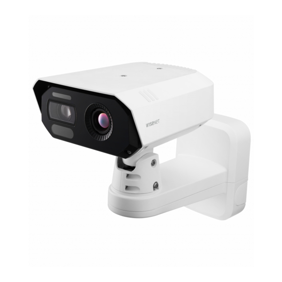
overview RECOMMENDED PC SPECIFICATIONS WHAT’S INCLUDED Please check if your camera and accessories are all included in the product package. ~ CPU : Intel(R) Core(TM) i7 3.4 GHz or higher (As for each sales country, accessories are not the same.) ~ RAM : 8G or higher ~ Recommended browser: Chrome Appearance... -
Page 7: At A Glance
AT A GLANCE Appearance Item Name Quantity Description Appearance Cable bushing Extra cable bushing for network cable installation Used to connect the RJ45 cable via a cable bushing to Cap Installer the PoE+ port Screwdriver bit Used when assembling or disassembling a wall mount Anchor bolt Used when fixing a mount plate to a wall Item... - Page 8 overview Internal composition (lower part of the mount) Internal composition (camera bottom) Item Description Zoom in (Tele) Item Description Zoom out (Wide) Used to discharge a lighting or a surge current outside in order to protect a camera from it Zoom/Focus Control Button Focus on a near object (Near) GND Terminal...
-
Page 9: Installation & Connection
installation & connection INSTALLATION Installation (mount plate) [If installing on a wall] This camera is waterproof and in compliance with the IP67 spec, but the jack connected to the external cable is not. You are recommended to install this product below the edge of eaves to prevent the cable from being externally exposed. 1-1. - Page 10 installation & connection [If installing it on a pillar] Installation (installing cables) 1-1. Select the pillar for installation, and check the height for where you want to install the camera. 2. Remove all the cable bushings at the lower part of the wall mount. 1-2.
- Page 11 3-3. Connect the cable bushing with the network cable inserted into the lower part of the wall mount as [Installation of the Power(DC 12V)/Audio/Alarm cable] shown in the figure. 4-1. Insert the cable bushings of the provided power/audio/alarm cables to the lower part of the mount, as shown in the figure.
- Page 12 installation & connection (When connecting the DC 12V power cable) Installation (wall mount) 4-3. Connect the provided power cable block to the power line. 5. Attach the lower part of the wall mount to the mount plate using a screwdriver bit. TR30 When connecting the power line to the power terminal block, paying attention to the polarity by referring to the imprint when 6.
-
Page 13: Inserting/Removing A Micro Sd Card
INSERTING/REMOVING A MICRO SD CARD 7. Attach the camera to the lower part of the mount using a screwdriver bit. Make sure to tighten the screws firmly so that there is no problem with waterproofing. Inserting a Micro SD card 1. -
Page 14: Connecting With Other Device
installation & connection Removing a Micro SD card CONNECTING WITH OTHER DEVICE Gently press down the exposed end of the Micro SD card to eject it from the slot. Grounding cable PoE+ Router Before removing the Micro SD card, in <Setup ( )>-<Event>-<Storage>, set the device to <Off>... - Page 15 Camera Setup 1. Connect an OTG adapter (5-pin) and a WiFi dongle to the micro USB port. Smartphone Setup 1. Install the Wisenet Installation application. 2. Select the camera SSID after turning on the WiFi. 3. Run the Wisenet Installation application.
- Page 16 If you want to connect an external device, you must turn it off before doing it. Before connecting a power plug to an outlet, connect the power cable to the camera and adapter first. Power Cable Specification In case of DC 12V Input: (TNM-C4940TD) Wire Type (AWG) Cable Length (Max.) (TNM-C4950TD/C4960TD) Wire Type (AWG) Cable Length (Max.)
- Page 17 Connecting to Audio Input/Output ~ Audio Codec - Audio In : G.711 PCM (Bit Rate: 64kbps / Sampling Frequency: 8kHz), G.726 ADPCM (Bit Rate: 16Kbps, 24Kbps, 32Kbps, 40Kbps / Sampling Frequency: 8kHz), AAC (Bit Rate: 48Kbps / Sampling Frequency: 16kHz) Speaker - Audio Out : G.711 PCM (Bit Rate: 64kbps / Sampling Frequency: 8kHz) ~ Full duplex Audio...
- Page 18 installation & connection Connecting to the I/O device Connecting to an external sensor Connect the Alarm I/O cable to the corresponding port of the port box. One of the signal lines (2 wires) of various sensors is connected to the [ALARM 1~4 (where the corresponding terminal is set as input)] terminal, and the other connected to the [GND] terminal.
-
Page 19: Network Connection And Setup
network connection and setup CONNECTING THE CAMERA DIRECTLY TO A DHCP BASED DSL/CABLE You can set up the network settings according to your network configurations. MODEM CONNECTING THE CAMERA DIRECTLY TO LOCAL AREA NETWORK Connecting to the camera from a local PC in the LAN 1. -
Page 20: Using Device Manager
network connection and setup USING DEVICE MANAGER If using a Broadband Router ~ IP Address : Enter an address falling in the IP range provided by the Broadband Router. Device manager program can be downloaded from <Technical Guides>-<Online Tool> menu at Hanwha Techwin website ex) 192.168.1.2~254, 192.168.0.2~254, (http://www.hanwha-security.com). -
Page 21: Registering Camera Manually
~ Example of the Dynamic IP environment configure the IP. TNM-C4940TD - If a Broadband Router, with cameras connected, is assigned an IP address by the DHCP server 2. Click < + > at the main page of the device manager. -
Page 22: Port Range Forward (Port Mapping) Setup
Port forwarding can be done without additional router setup if the router supports the UPnP (Universal Plug and Play) function. For more information, refer to the user manual of the applicable router. After connecting the network camera, select the checkbox from the menu <Quick connect> in <Wisenet DDNS> in “Settings -> Network -> DDNS”. -
Page 23: Connecting To The Camera From A Shared Local Pc
2. From the remote PC, launch the Internet browser and type the DDNS URL address of the camera, or the IP address of the Broadband Router in the address bar. ex) http://ddns.hanwha-security.com/ID To use Wisenet DDNS, sign up at the Wisenet DDNS homepage (http://ddns.hanwha-security.com) and register the product at [My DDNS]>[Register Product]. English _23... -
Page 24: Connecting To The Camera
To register your device to the <DDNS> server, visit http://ddns.hanwha-security.com and register your device 1. Launch the Internet browser. first, and then set the Web Viewer’s <Network> - <DDNS> to <Wisenet DDNS>, as well as providing 2. Type the IP address and HTTP port number of the camera in the address bar. -
Page 25: Password Setting
PASSWORD SETTING CAMERA WEB VIEWER SETUP When you access a camera for the first time, you must register its 1. Click the [Setup ( )] icon. login password. 2. The Settings window appears. 3. You can configure settings for the camera’s basic information, video, audio, network, event, analysis, and system over the network. -
Page 26: Troubleshooting
appendix TROUBLESHOOTING PROBLEM SOLUTION PROBLEM SOLUTION When an Windows 10 user accesses ~ Verify the settings in the following sequence: <Motion detection> of <Analytics> is ~ This is what happens when microphone driver has been set to Realtek driver. the web viewer through Chrome set to <Enable>, but no notification A. - Page 27 Any changes or modifications in construction of this device which are not expressly approved by the party responsible for compliance could void the user's authority to operate the equipment. This device complies with part 15 of the FCC Rules. Operation is subject to the following two conditions: (1) This device may not cause harmful interference, and (2) this device must accept any interference received, including interference that may cause undesired operation.
Need help?
Do you have a question about the TNM-C4940TD and is the answer not in the manual?
Questions and answers