
Related Manuals for Baileigh Industrial TN-800

Summary of Contents for Baileigh Industrial TN-800
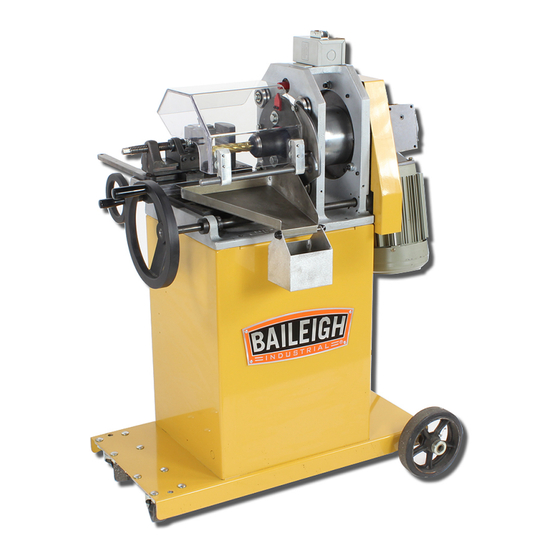
- Page 1 OPERATOR’S MANUAL TUBE AND PIPE NOTCHER MODEL: TN-800 (B8550) © 2015 Baileigh Industrial, Inc.
-
Page 2: Table Of Contents
Table of Contents INTRODUCTION ......................1 GENERAL NOTES ......................1 SAFETY INSTRUCTIONS ....................2 SAFETY PRECAUTIONS ....................5 TECHNICAL SPECIFICATIONS ..................7 UNPACKING AND CHECKING CONTENTS ..............8 Cleaning ........................8 TRANSPORTING AND LIFTING ..................9 INSTALLATION ....................... 9 ASSEMBLY AND SET UP .................... 10 GETTING TO KNOW YOUR MACHINE ............... -
Page 3: Introduction
INTRODUCTION The quality and reliability of the components assembled on a Baileigh Industrial machine guarantee near perfect functioning, free from problems, even under the most demanding working conditions. However if a situation arises, refer to the manual first. If a solution cannot be found, contact the distributor where you purchased our product. -
Page 4: Safety Instructions
Note: This symbol refers to useful information throughout the manual. IMPORTANT PLEASE READ THIS OPERATORS MANUAL CAREFULLY It contains important safety information, instructions, and necessary operating procedures. The continual observance of these procedures will help increase your production and extend the life of the equipment. SAFETY INSTRUCTIONS LEARN TO RECOGNIZE SAFETY INFORMATION This is the safety alert symbol. - Page 5 SAVE THESE INSTRUCTIONS. Refer to them often and use them to instruct others. PROTECT EYES Wear safety glasses or suitable eye protection when working on or around machinery. PROTECT AGAINST NOISE Prolonged exposure to loud noise can cause impairment or loss of hearing.
- Page 6 BEWARE OF PIERCING POINTS NEVER place Keep hands, fingers, or any part of your body away from rotating tooling bit. CUTTING HAZARD Keep hands and fingers away from the rotating cutters. These rotating cutters can be extremely dangerous if you do not follow proper safety procedures.
-
Page 7: Safety Precautions
SAFETY PRECAUTIONS Metal working can be dangerous if safe and proper operating procedures are not followed. As with all machinery, there are certain hazards involved with the operation of the product. Using the machine with respect and caution will considerably lessen the possibility of personal injury. However, if normal safety precautions are overlooked or ignored, personal injury to the operator may result. - Page 8 10. Use eye and ear protection. Always wear ISO approved impact safety goggles. Wear a full- face shield if you are producing metal filings. 11. Do not overreach. Maintain proper footing and balance at all times. DO NOT reach over or across a running machine.
-
Page 9: Technical Specifications
TECHNICAL SPECIFICATIONS Mill Speed 177rpm Maximum Notching Capacity 3" Diameter using a 1" end mill (76mm / 25mm) .5" Diameter using a .5" end mill and .5" reducer bushing Minimum Notching Capacity (12mm / 12mm / 12mm) Angle Adjustment 0 – 60° End Mill Size 1"... -
Page 10: Unpacking And Checking Contents
UNPACKING AND CHECKING CONTENTS Your Baileigh machine is shipped complete in one crate. Separate all parts from the packing material and check each item carefully. Make certain all items are accounted for before discarding any packing material. WARNING: SUFFOCATION HAZARD! Immediately discard any plastic bags and packing materials to eliminate choking and suffocation hazards to children and animals. -
Page 11: Transporting And Lifting
TRANSPORTING AND LIFTING IMPORTANT: Lifting and carrying operations should be carried out by skilled workers, such as a truck operator, crane operator, etc. If a crane is used to lift the machine, attach the lifting chain carefully, making sure the machine is well balanced. Follow these guidelines when lifting with truck or trolley: •... -
Page 12: Assembly And Set Up
• Remove scrap and waste materials regularly, and make sure the work area is free from obstructing objects. • If long lengths of material are to be fed into the machine, make sure that they will not extend into any aisles. •... -
Page 13: Getting To Know Your Machine
Creating a perfect weld joint when mating two or more pieces of tubing together. • The TN-800 Notching Machine you have purchased is built of solid steel and high quality components, ensuring maximum rigidity and long life. - Page 14 Item Description Function Swivel Casters Steer and control the machine when moving. Rotates the spindle head on the oscillation plate to Large Feed Wheel create the eccentric pattern used for milling. Used to move the vise bed along the length of the end Y Feed Hand Wheel mill.
-
Page 15: Electrical
ELECTRICAL CAUTION: HAVE ELECTRICAL UTILITIES CONNECTED TO MACHINE BY A CERTIFIED ELECTRICIAN! Check if the available power supply is the same as listed on the machine nameplate. WARNING: Make sure the grounding wire (green) is properly connected to avoid electric shock. DO NOT switch the position of the green grounding wire if any electrical plug wires are switched during hookup. -
Page 16: Plug Connection
• Improper connection of the equipment-grounding conductor can result in risk of electric shock. The conductor with insulation having an outer surface that is green with or without yellow stripes is the equipment-grounding conductor. If repair or replacement of the electric cord or plug is necessary, do not connect the equipment-grounding conductor to a live terminal. -
Page 17: Operation
OPERATION CAUTION: Always wear proper eye protection with side shields, safety footwear, and leather gloves to protect from burrs and sharp edges. WARNING: BEFORE THE MAIN LEXAN GUARD IS OPENED, THE POWER CORD MUST BE UNPLUGGED FROM ITS SOURCE. Cutter Selection 1. -
Page 18: Material Insertion
Material Insertion 1. Once the proper cutter is installed, the material to be notched can be inserted into the vise. 2. Open the vise and insert the material so that the end toward the cutter extends past the vise jaw approximately 2" (50.8mm). Material should be kept as close as possible to the vise jaws to get accurate notches. -
Page 19: Setting Offset
Setting Offset 1. Once the cutter and material are installed, the cutter offset can be set. 2. If using the 1’ (25.4mm) cutter on 1” (25.4mm) material or the 1/2" (12.7mm) cutter on 1/2” (12.7mm) material, set the machine to the “12 o’clock” position (fine tune as needed) and move on to setting any desired angle and notching the material. -
Page 20: Notching
Notching 1. Activate the start switch making sure the cutter is rotating the correct way. With the cutter rotating, the notch can be created. 2. Using the large feed hand wheel, slowly rotate in the counter clockwise direction. As the cutter makes contact with the material, continue to rotate feeding slow enough not to damage the cutter. -
Page 21: Repeat Notching
Repeat Notching 1. For repeat notching perform the above steps and document the number on the counter. This number can also be used to make precise notches to the depth desired. The calibration of the counter is: Actual distance in Counter display inches 0000.0... -
Page 22: Material Selection
MATERIAL SELECTION CAUTION: It must be determined by the customer that materials being processed through the machine are NOT potentially hazardous to operator or personnel working nearby. When selecting materials keep these instructions in mind: • Material must be clean and dry. (without oil) •... -
Page 23: Troubleshooting
TROUBLESHOOTING WARNING: Make sure the electrical disconnect is OFF before working on the machine. Problem Solution Material too far out past vise Material not clamped tight in vise Vise lock lever is too loose Chattering Cutter is dull or loose "X","Y"... -
Page 24: Electrical Schematic
ELECTRICAL SCHEMATIC... -
Page 25: Lubrication And Maintenance
LUBRICATION AND MAINTENANCE WARNING: Make sure the electrical disconnect is OFF before working on the machine. Maintenance should be performed on a regular basis by qualified personnel. Always follow proper safety precautions when working on or around any machinery. • Check daily for any unsafe conditions and fix immediately. •... -
Page 26: Parts Diagram
PARTS DIAGRAM Base Assembly... -
Page 27: Spindle Assembly
Spindle Assembly... -
Page 28: Forward Riser Assembly
Forward Riser Assembly... -
Page 29: Motor And Gearbox Assembly
Motor and Gearbox Assembly... -
Page 30: Rear Riser Assembly
Rear Riser Assembly... -
Page 31: Crank Shaft Assembly
Crank Shaft Assembly... -
Page 32: Vise Assembly
Vise Assembly... -
Page 33: Slide Base Assembly
Slide Base Assembly Parts List... - Page 34 Item Part Number Description Qty. ME-M800-6A067 M800 Main Frame (Metric) M10 X 1.5 X 35 Hex Flange Flatwasher Imperial M10 X 1.5 Hex Flange Nut ME-M800-7A041 Adjustable Bushing ME-M800-7A040 Non Adjusting Bushing PP-0091 V Roller ME-M800-6A095 Straddle Bracket PP-0086 Cam Follower PP-0087 Adjustable Cam Follower M800-7A029...
- Page 35 Item Part Number Description Qty. PP-0053 0.75 ID X 0.875 OD X 0.75 Wide ME-M800-7A020 Bearing Block M6 X 1.0 X 30 SHCS PP-0094 Outer Race PP-0095 IR-1216 (0.75 ID X 1.0 OD X 1.03 LG) M800-7A009 Handle Shaft Imperial .1875 X 1 Keystock PP-0150 30 Tooth Sprocket...
- Page 36 Item Part Number Description Qty. M8 X 1.25 X 40 SHCS ME-M800-6A025 Base Plate ME-M800-6A072 End Block PP-0168 .625 ID X 1.0 OD X .0625 LG M8 X 1.25 X 20 SHCS PP-0167 0.625 ID X 0.75 OD X 0.625 LG M800-7A019 Long Lead Screw PP-0169...
- Page 37 Item Part Number Description Qty. M800-7A022 Vise Spacer M12 X 1.75 X 35 Hex Flange M8 X 1.25 X 16 SHCS ME-M800-7A010 Guard Spacer M800-6A089 Tapered Chip Tray M800-7A031 Guard Shaft M800-6A096 Lexan Guard ME-M800-6A098 Guard Pivot M6 X 1.0 X 14 SHCS M800-6A091 Chip Bin...
- Page 38 NOTES...
- Page 39 NOTES...
- Page 42 General Machinery Safety Instructions Machinery House requires you to read this entire Manual before using this machine. 1. Read the entire Manual before starting 14. Use correct amperage extension cords. machinery. Machinery may cause serious injury if Undersized extension cords overheat and lose not correctly used.
- Page 43 Pipe/Tube Notcher-Electric Safety Instructions Machinery House requires you to read this entire Manual before using this machine. 11. Secure Material. 1. Maintenance. During the notching process, Make sure the Pipe/Tube Notcher the workpiece must always be secured in the work is turned off and disconnect from the main power holding vice.