Table of Contents
Advertisement
Quick Links
Installation and operating instructions for the X10 PowerFlash
Universal Interface, Model PF284
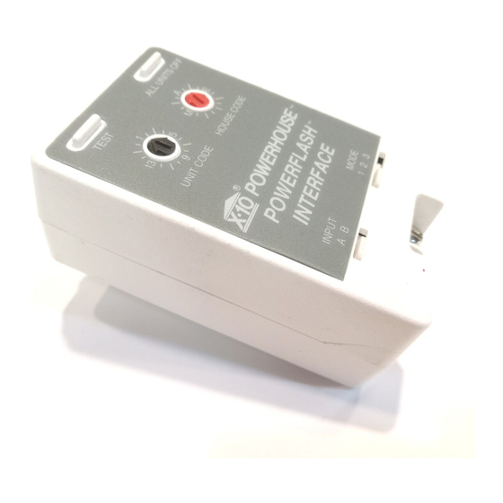
The Powerfl ash Universal Interface provides a way to
interface to conventional security systems, and other contact
closure or voltage output devices, to control X10 powerline
controlled products, to turn on lights, fl ash lights, activate
plug-in alarm sirens, etc.
The Powerfl ash Interface has terminals for two types of
inputs, determined by the INPUT slide switch:
Position A: 6-18 VDC
Position B: Dry contact closure
Setting up the Powerfl ash Interface
• Use a small screwdriver to set the desired House Code and Unit Code A-P and 1-16.
• Adjust the MODE slide switch to select the desired mode of operation as follows:
1. Turns on all Lamp Modules and Wall Switch Modules set to the same Housecode
as the Powerfl ash Interface. Also turns on Appliance Modules set to the same
Housecode and Unit Code as the Powerfl ash Interface. When the alarm is reset,
only the Modules set to the same Housecode and Unit Code as the Powerfl ash
Interface are turned off.
2. Flashes all Lamp Modules and Wall Switch Modules set to the same Housecode
as the Powerfl ash Interface. When reset all lights stay on.
3. Turns on Lamp Modules and Appliance Modules set to the same Housecode and
Unit Code as the Powerfl ash Interface. When reset, turns the same Module off.
• Connect the terminals on the Powerfl ash Interface to the burglar alarm or output
device such as a driveway sensor or similar contact closure.
Note: Observe the polarity shown on the unit if the alarm output is DC voltage.
• Plug the Powerfl ash Interface into a 120V AC wall outlet.
Testing the Interface
• Press TEST to activate the Powerfl ash Interface according to the selected mode.
• Press ALL UNITS OFF to turn off Modules left on after activating the Interface.
TM
TEST
ALL UNITS OFF
1
A
13
5
M
E
9
I
POWERFLASH INTERFACE
For more information on X10 products and
INPUT
MODE
A
B
1
2
3
Do not connect 120V
to the terminals!
X10.com, a division of X10 Wireless Technology, Inc. (X10) warrants X10 products to be
free from defective material and workmanship for a period of 90 days from the original date
of purchase at retail. X10 agrees to repair or replace, at it's sole discretion, a defective X10
product if returned to X10 within the warranty period and with proof of purchase.
If service is required under this warranty:
1. Visit www.x10.com/support/return_policy.htm, or e-mail sales@x10.com to obtain a
Return Merchandise Authorization (RMA) number.
2. Return the defective unit postage prepaid to X10 (see address on back).
3. Enclose a check for $4.00 to cover postage and handling.
4. Enclose a dated proof of purchase.
5. X10 is not responsible for shipping damage. Units to be returned should be packed
carefully.
Please visit www.x10.com/support for help.
Check Out our Web site at:
http://www.x10.com
special promotional offers.
X10 Wireless Technology, Inc. 90 Day Limited Warranty
PF284-6/13
Advertisement
Table of Contents

Related Manuals for X10 PowerFlash PF284


Summary of Contents for X10 PowerFlash PF284
- Page 1 Housecode and Unit Code as the Powerfl ash Interface. When the alarm is reset, of purchase at retail. X10 agrees to repair or replace, at it’s sole discretion, a defective X10 only the Modules set to the same Housecode and Unit Code as the Powerfl ash product if returned to X10 within the warranty period and with proof of purchase.
- Page 2 Maxi Controller SC503 Screws in to an existing light fi xture. Controls Rockaway, NJ 07866 Lets you control up to 16 X10 Modules at up to 150W, incandescent only. the touch of a button from anywhere in the Appliance Module - AM486/AM466 house.
Need help?
Do you have a question about the PowerFlash PF284 and is the answer not in the manual?
Questions and answers