
Related Manuals for SMAC LAC-26

Summary of Contents for SMAC LAC-26
- Page 1 SMAC LAC-26 ECHNICAL EFERENCE ANUAL Revision 0, April 2013 SMAC CORP. 5807 Van Allen Way Carlsbad, CA 92008...
- Page 2 S.M.A.C. 5807 V LLEN , CA 92008 ARLSBAD : 1-760-929-7575 / F : 1-760-929-7588 HONE : 1-760-929-7575 ECHNICAL SSISTANCE © C . 1993 - 2013 OPYRIGHT UTOMATION ODULES...
-
Page 3: Table Of Contents
SMAC LAC-26 Technical Reference Manual TABLE OF CONTENTS 1. Introduction..........................3 1.1 Specifications........................4 1.2 Digital I/O Interface......................5 1.2.1 Dedicated Digital Inputs ....................5 1.2.2 General Purpose Inputs ....................5 1.2.3 General Purpose Outputs ....................6 1.2.4 Digital I/O "States" ....................... 6 1.2.5 I/O Technical Specifications.................. - Page 4 6.1.1 Initial Setup and Configuration..................73 6.1.2 Commutation........................ 74 Appendix 1. Specification......................77 Appendix 2 Outline drawing...................... 78 Aooendix 3. Connector Pin Definitions..................80 Appendix 4 – Summary of LAC-26 Commands ..............81 Appendix 5 AMC Driver Troubleshooting................82 4/29/2013...
-
Page 5: Introduction
LAC-26 Technical Reference Manual 1. Introduction The LAC-26 is a two axis stand-alone integrated controller / driver, with input / output (I/O) capabilities similar to the LAC-25. The first axis is for the control of DC brush type motors or actuators with its integrated driver. -
Page 6: Specifications
SMAC LAC-26 Technical Reference Manual 1.1 Specifications Description Stand-Alone 2 Axis Servo Motor Controller / Driver Operating Modes Position, Velocity, Torque, Electronic Gearing Control Algorithm Max. Servo Loop Rate 100 µS per enabled axis Servo Position Feedback Incremental Encoder with Index Output (Standard) PWM Motor Drive, Single Phase (brushed), 3 Amps Cont. -
Page 7: Digital I/O Interface
Figure 1 illustrates one of the LAC-26’s dedicated digital inputs. These inputs are Limit+, Limit-, Home and Fault for both axis of the LAC-26. The power to activate these inputs is provided by the LAC- 26 so it is only necessary to complete the circuit to activate the input. -
Page 8: General Purpose Outputs
Figure 3 illustrates one of the LAC-26’s general purpose outputs. These outputs are galvanically isolated from the LAC-26. When an output is activated, positive current will flow from the collector of the optocoupler transistor (the output pin) to it’s emitter (the output return pin), Figure 3. -
Page 9: I/O Technical Specifications
Table 4: Dedicated I/O Specifications 1.3 Encoder Interface The LAC-26 has two channels of quadrature type encoder interface with optional index signal input and the ability to supply +5 VDC at a minimum of 50 mA (or greater depending on other demands put on the internal 5 VDC power supply). -
Page 10: Output Driver Interface
(e.g.,: oscilloscope monitoring of following error or output command). 1.5 Analog to Digital Conversion (A/D) Interface The LAC-26 provides a 5 channel, 10 bit A/D conversion interface with a +10 VDC reference and analog ground. For reverse compatibility purposes the A/D interface is actually ten channels but the user is only given access to channels 0, 1 and 2 while channels 6 and 7 are used internally for monitoring the output current of the onboard drivers. -
Page 11: The Interrupt Vector Table
SMAC LAC-26 Technical Reference Manual 2.1 The Interrupt Vector Table The Interrupt Vector Table consists of an entry for each interrupt source and each entry will correspond to that interrupt's level (level 0 = entry 0, level 1 = entry 1, etc.). A particular table entry must be loaded with the number of a valid macro to be executed should that interrupt source become active. -
Page 12: Interrupt Priority
SMAC LAC-26 Technical Reference Manual The Axis Fault interrupts indicate that a fault condition (usually an over-temperature condition) has arisen. Normally, when this condition is detected, the servo is disabled and the "Fault" bit in that axis' status word is set. If the interrupt for this condition is enabled, the "Fault" bit will still be set but the servo will not be disabled. -
Page 13: Entering Commands
(EF) command; otherwise, the Echo On (EN) command (which is the default mode) should be issued. If you enter an invalid command, the LAC-26 will respond with a question mark "?" followed by a code indicating the type of error and the Status LED will begin to blink. These codes are listed in Appendix A, LAC-26 Error Code Definitions. -
Page 14: Downloading Commands
Microsoft Windows Terminal program. Whatever communications software is used, it must have the ability to provide a short delay (approx. 100 mS) after transmitting each line to give the LAC-26 time to interpret and store the commands that were just sent. - Page 15 SMAC LAC-26 Technical Reference Manual aFAn -- Feed-forward, Acceleration -- Command: Argument: 0 <= n <= 32767 Default: This command allows for the adjustment of the PID digital filter acceleration feed-forward term for servo axis 'a'. During the course of a Position Mode (PM) or Velocity Mode (VM) move, at any point during acceleration or deceleration (with a consistent load), the ideal required value of the servo output is fairly consistent and somewhat predictable.
- Page 16 SMAC LAC-26 Technical Reference Manual aFVn -- Feed-forward, Velocity -- Command: Argument: 0 <= n <= 32767 Default: This command allows for the adjustment of the PID digital filter velocity feed-forward term for servo axis 'a'. During the course of a Position Mode (PM) or Velocity Mode (VM) move, at any point along the way (with a consistent load), the ideal required value of the servo output is fairly consistent and somewhat predictable.
- Page 17 Interrupt only In all cases, the Error flag in the status word will be set. This will prevent the LAC-26 from moving the servo until the flag is cleared by issuing the Motor On (MN) command. Before this command will have any effect, the limit switch must be enabled with the Limit Switch On command (LN).
- Page 18 SMAC LAC-26 Technical Reference Manual Command: aOMn -- Output Mode -- Argument: 0 <= n <= 255 Default: This command allows the user to determine what data gets sent to the D/A analog output for a given axis. The upper four bits of the argument are for redirection of data and determine from which axis the D/A channel will get it’s data.
- Page 19 SMAC LAC-26 Technical Reference Manual Command: aPHn -- Set Servo Phasing -- Argument: 0 <= n <= 63 Default: This command is used to set the output polarity, encoder phasing, Index input sense, Home input sense, Limit+ and Limit- input sense for servo axis ‘a’. The polarity of the output will determine whether the servo is driven in a direction that reduces or increases position error.
- Page 20 SMAC LAC-26 Technical Reference Manual aSAn -- Set Acceleration -- Command: Argument: 0 <= n < 1,073,741,823 Default: This command sets the acceleration rate for servo axis 'a'. The 32 bit argument to this command is scaled by 65536. This number determines how much the servo's velocity will be altered by each servo loop interval (determined by the Servo Speed "SS"...
- Page 21 SMAC LAC-26 Technical Reference Manual Command: aSGn -- Set Proportional Gain -- Argument: 0 <= n <= 32,767 Default: This command sets the proportional gain term of the PID digital filter loop for servo axis 'a'. Related Commands: SI, SD, IL...
- Page 22 Argument: 1 <= n <= 255 Default: This command sets the servo loop interval, which is the same for both axis' of the LAC-26. The period of this interval can be calculated by the following: T = (n) * 0.000100 where "T"...
-
Page 23: Reporting Commands
Related Commands: SA, SS 4.2 Reporting Commands The reporting commands output data relevant to the operating status of the LAC-26. Numerical output will be in the mathematical base determined by the Decimal Mode (DM) / Hexadecimal Mode (HM) commands and output will be followed by a carriage return and linefeed. - Page 24 SMAC LAC-26 Technical Reference Manual -- Tell State of I/O Channel 'n' -- Command: Argument: 0 <= n <= 63 Default: "Off" This command reports the current state of the I/O channel specified by 'n' and what type of logic the channel is (either active "on"...
- Page 25 SMAC LAC-26 Technical Reference Manual Command: aTKn -- Tell (K) Constants -- Argument: 0 <= n <= 1 This command will display a number of internal settings depending on the value specified by 'n'. If 'n' is "0" or is not specified, then various parametric values for the servo axis specified by 'a' will be displayed.
- Page 26 "MD" and the individual macro number. This is useful when downloading programs from the LAC-26 to a computer in that you need not re-enter the Macro Define (MD) command and number at the beginning of each macro.
- Page 27 SMAC LAC-26 Technical Reference Manual -- Tell Status Word -- Command: This command reports the operating status word of servo axis 'a'. The response is coded into a single 32 bit value. The meaning of each bit is listed below: Purpose Servo Enabled.
- Page 28 SMAC LAC-26 Technical Reference Manual Reserved. Limit Mode Abort. Used by Limit Mode (LM) to determine what action to take upon the occurrence of a limit switch event. Limit Mode Stop. Used by Limit Mode (LM) to determine what action to take upon the occurrence of a limit switch event.
-
Page 29: Motion Commands
SMAC LAC-26 Technical Reference Manual 4.3 Motion Commands Motion Commands are those commands that involve or cause the actual movement of a servo. Any position mode (PM) based motion will be carried out using a trapezoidal velocity profile with the maximum velocity determined by the Set Velocity (SV) command. - Page 30 SMAC LAC-26 Technical Reference Manual Command: -- Enable Axis for Operation -- Default: Axis 1 and 2 enabled. This command will disable operation of servo axis 'a'. Because no operation may be made on a disabled axis, the equivalent of a Motor Off (MF) command is executed before the axis is disabled.
- Page 31 SMAC LAC-26 Technical Reference Manual Command: aEGn -- Electronic Gearing Mode -- Argument: -2 <= n <= 2 Default: Position Mode This command causes (slave) servo axis 'a' to begin to move proportionally to (master) servo axis 'n'. If 'n' is "0" then the electronic gearing mode for axis 'a' will be disabled. If 'n' is positive then the slave axis will track the master axis' optimal position (or that which is reported by the TO command).
- Page 32 SMAC LAC-26 Technical Reference Manual Command: -- Go (start motion) -- This command causes servo axis 'a' to begin motion. When in the Velocity Mode (VM), the axis will accelerate to a constant velocity. When in the Position Mode (PM) the axis will begin to seek the specified target position.
- Page 33 PM or VM. For mode 1 (or QM1), the LAC-26 will use one of its A/D channels to monitor servo output current and attempt to maintain that output current at a steady level as commanded by the user program (see the SQ and SC commands).
- Page 34 SMAC LAC-26 Technical Reference Manual Command: aSEn -- Set Maximum Following Error -- Argument: 0 <= n <= 16,383 Default: 16,383 This command is used to set the maximum allowable following error (difference between the actual position and the optimal position) for servo axis 'a'. If the following...
-
Page 35: Register Commands
In certain applications, the user may find it necessary to use data pertinent to the internal operation of the LAC-26. This may be accomplished via the use of the Read Byte (RB), the Read Word (RW) and the Read Long (RL) commands which copy the LAC-26's internal RAM memory to the accumulator and the Write Byte (WB), the Write Word (WW) and the Write Long (WL) commands which copy the accumulator to the LAC-26's internal RAM memory. - Page 36 SMAC LAC-26 Technical Reference Manual Status Status word (TS command). Peak velocity (SV command). Negative peak velocity (SV command). Temporal velocity (TV command). Desp Desired position (TT command). Carp Temporal desired position (TO command). Acceleration constant (SA command). Curp Current real position (TP command).
- Page 37 Pause. This bit is set to “1” when the space bar is used to pause a user program. SXOff. This bit is set to “1” when the LAC-26 receives an XOFF code. HexMod. This bit is set to “1” by the HM command and set to “0” by the command.
- Page 38 SMAC LAC-26 Technical Reference Manual Variable Type Axis #1 Address Axis #2 Address Name Status LONG 01C0H/0448 0250H/0592 LONG 01C6H/0454 0256H/0598 LONG 01CAH/0458 025AH/0602 LONG 01CEH/0462 025EH/0606 Desp LONG 01E0H/0480 0270H/0624 Carp LONG 01E6H/0486 0276H/0630 LONG 01EAH/0490 027AH/0634 Curp LONG...
- Page 39 SMAC LAC-26 Technical Reference Manual AIN8 WORD 0610H/1552 AIN9 WORD 0612H/1554 VERSION WORD 0616H/1558 LST_ERR BYTE 0619H/1561 LTIMER WORD 061AH/1562 ADSEMA WORD 061CH/1564 SYSSTAT WORD 0712H/1810 IPEND0 WORD 0718H/1816 IPEND1 WORD 071AH/1818 SCLOCK LONG 0722H/1826 RCLOCK LONG 0726H/1830 IO_DELAY BYTE...
- Page 40 SMAC LAC-26 Technical Reference Manual Command: -- Exclusive-Or Accumulator with 'n' -- Argument: -2,147,483,647 <= n <= 2,147,483,647 This command causes the result of an exclusive-OR of the accumulator with 'n' to reside in the accumulator. Command: -- Load Accumulator with 'n' (Signed) -- Argument: -2,147,483,647 <= n <= 2,147,483,647...
- Page 41 SMAC LAC-26 Technical Reference Manual Related Commands: AR Command: -- Read Byte (8 bits) at RAM location 'n' Argument: 0 <= n <= 2047 This command reads the 8 bit value at internal RAM location 'n' and copies it to the low 8- bits of the accumulator while clearing the upper 24 bits.
- Page 42 SMAC LAC-26 Technical Reference Manual Related Commands: SL Command: -- Tell Contents of Register 'n' -- Argument: 0 <= n <= 511 This command reports the value contained by Register 'n'. Command: -- Write Byte (8 bits) to RAM location 'n' -- Argument: 0 <= n <= 2047...
-
Page 43: Sequence Commands
SMAC LAC-26 Technical Reference Manual 4.5 Sequence Commands The LAC-26 includes commands that provide for conditional sequence command execution based on the register data, I/O state and etc. These Sequence Commands are illustrated by the following general forms: If the condition is true, command execution will continue normally. If the condition •... - Page 44 SMAC LAC-26 Technical Reference Manual Command: -- If Bit 'n' of Accumulator is Clear (0) -- Argument: 0 <= n <= 31 If bit 'n' of the accumulator is clear (equals 0), command execution will continue; otherwise, the next two commands in the command line or the macro will be skipped.
- Page 45 SMAC LAC-26 Technical Reference Manual Command: aIPn -- Interrupt on Absolute Position 'n' -- Argument: -2,147,483,647 <= n <= ,147,483,647 This command is used to determine when servo axis 'a' has achieved the specified position 'n' referenced by the home position (or zero). When that position has been reached, "breakpoint reached"...
- Page 46 SMAC LAC-26 Technical Reference Manual Command: -- Wait ÔnÕ milliseconds -- Argument: 0 <= n <= 65,535 This command causes a wait period of 'n' milliseconds before going on to the next command. Command: aWEn -- Wait for Edge -...
- Page 47 SMAC LAC-26 Technical Reference Manual This command is used to determine when servo axis 'a' has achieved the specified position 'n' referenced by the home position (or zero). Until that position has been reached, command execution will be suspended. This command can be issued before or after the servo has been commanded to move;...
-
Page 48: Learned Position Storage (Lps) Commands
LAC-26 Technical Reference Manual 4.6 Learned Position Storage (LPS) Commands The LAC-26 uses part of its nonvolatile RAM (NVRAM) to create a 256 item table for storing positions. This table overlaps the last 256 registers of the register table. The LPS table is normally accessed by three commands: Learn Position (LP), Learn Target (LT) and Move to Position (MP). -
Page 49: Macro Commands
It should be noted that macros can use indirect as well as direct arguments. The LAC-26 allows for the creation of 256 macros consisting of a total of nearly 2,300 command instructions. - Page 50 SMAC LAC-26 Technical Reference Manual Command: -- Jump to Command, Absolute -- Argument: 0 <= n <= 31 This command causes execution of a macro to jump to the absolute command specified by 'nÕ. Commands are numbered sequentially starting from 0. If 'n' is specified whereas the command would attempt to jump past the end of the macro, command execution will resume as i f the macro had ended.
- Page 51 This command may be used to "Jump" to a previously defined macro command. Once the LAC-26 begins executing the new macro, it has no record of how it got there. This means that any commands that appear after the Macro Jump (MJ) command will not be executed. If there is n o macro defined by the number 'n', an error will be reported.
- Page 52 "MD" and the individual macro number. This is useful when downloading programs from the LAC-26 to a computer in that you need not re-enter the Macro Define (MD) command and number at the beginning of each macro.
-
Page 53: Input / Output (I/O) Commands
LAC-26 Technical Reference Manual 4.8 Input / Output (I/O) Commands The user is able to manipulate the LAC-26's I/O channels via the use of several commands. These include setting or clearing outputs, reading inputs and altering the logic type of both. - Page 54 SMAC LAC-26 Technical Reference Manual Command: -- Make I/O Channel 'n' Active Low -- Argument: 0 <= n <= 63 Default: Active high or active "on" This command causes I/O channel 'n' to assume an active "off" mode. Related Commands: CH Command: -- Turn I/O Channel 'n' "On"...
-
Page 55: Future Expansion Interface
LAC-26 Technical Reference Manual 4.9 Future Expansion Interface For future expansion, the LAC-26 provides a proprietary high speed serial data bus. Such uses might include various external devices such as thumb-wheel switches, LED or LCD displays, switch panels and additional number or types of input and output. This provides custom expansion flexibility in certain qualified OEM applications. -
Page 56: Serial Communications And Miscellaneous Commands
LAC-26 Technical Reference Manual 4.10 Serial Communications and Miscellaneous Commands These commands control operation of the serial communication's interface and cover the balance of the LAC-26 functions not fitting in the other categories. Command: -- Break -- This command will cause the rest of the command line or macro to be skipped. This command is used along with the Sequence Commands for conditional command execution. - Page 57 SMAC LAC-26 Technical Reference Manual Command: -- Capture Data -- Argument: 0 <= n <= 16383 This command allows for the capture and recording of data from an internal variable with the user being able to later download and plot this data for analysis. The number of samples that can be recorded depends on the amount of macro memory available at the time that the Capture Storage (CS) command is issued.
- Page 58 SMAC LAC-26 Technical Reference Manual Command: -- Capture Storage -- Argument: 0 <= n <= 16383 This command is used to allocate storage space for the data recorder commands. T h e argument determines the maximum number of samples that can be recorded. If an argument is used that is greater than the macro memory available, then an error will be reported.
- Page 59 SMAC LAC-26 Technical Reference Manual Command: -- Echo On -- Default: Echo On This command causes characters received from the serial communication's interface to b e echoed as they are received. It is normally used in the full-duplex mode of operation in serial communications.
- Page 60 (see Sequence Commands). Command: -- Reset -- This command performs a complete restart of the LAC-26, including restoration of a l l default conditions, such as acceleration and velocity, and leaves all servo axis' in the "off" state. 4/29/2013...
- Page 61 SMAC LAC-26 Technical Reference Manual Command: VI[[""][:n][:N]] -- Variable Input -- Argument: 0 <= n <= 255 This command allows for the display of an optional text string, an optional carriage return / linefeed (CRLF) and the entry of integer numeric operator input to a register variable.
- Page 62 Argument: n = 123 This command re-formats and re-initializes the LAC-26's non-volatile static ram (NVRAM). This means that any macros will be deleted and their space recovered, register contents will be set to 0 and the baud rate (among other things) will be set to their default values. Evidence of the baud rate change will not be immediate but will occur when the unit is either power cycled or the Reset (RT) command is issued.
- Page 63 7 - OUT OF MACRO SPACE. The LAC-26 allows for a maximum of 256 macros with up to 256 commands per macro a n d approximately 15800 bytes of macro storage space. Each macro command requires 6 bytes o f macro storage memory and each macro requires an overhead of 1 byte.
- Page 64 This error indicates that the memory space set aside for this purpose has been exhausted and no more "calls" may b e attempted. The LAC-26 is capable of macro calls nested 25 deep. 12 - MACRO MUST BE FIRST COMMAND.
-
Page 65: Amc Driver Setup
SMAC LAC-26 Technical Reference Manual 5. AMC driver setup 5.1 Communication Protocol DZ digital drives offer networking capability through either CANopen or RS-485 communication: CANopen is used with DZC drives, and RS-485 is used with DZR drives. Both DZC and DZR drives include an auxiliary RS- 232 serial port used for configuring the drive through DriveWare. -
Page 66: Control Modes
SMAC LAC-26 Technical Reference Manual 5.2 Control Modes The DZ family of digital drives operate in a variety of control modes. The setup and configuration parameters for these modes are commissioned through DriveWare. See the DriveWare Software Guide for mode configuration information. -
Page 67: Feedback Supported
SMAC LAC-26 Technical Reference Manual drive interpolates between command points, defining the rate by dividing the change in command by the interpolation time period. This allows the drive to respond smoothly to each step in command. Cyclic Synchronous Current In Cyclic Synchronous Current Mode, the drive closes the current loop. The host is allowed more control by having the ability to instantly add current feedforward values. -
Page 68: Encoder Feedback
SMAC LAC-26 Technical Reference Manual Yes youFor more information on using Hall Sensors for trapezoidal commutation, see “Trapezoidal Commutation” on page 74. Note Users designing their own PCB interface may also design the appropriate circuitry on their PCB interface to allow differential inputs 5.2.8 Encoder Feedback... -
Page 69: Vdc Position
SMAC LAC-26 Technical Reference Manual DZ drives can also use encoder feedback for sinusoidal commutation by using the AutoCommutation routine in DriveWare. Encoder feedback is also used in the "Phase Detect" procedure in DriveWare, which is necessary when using a three phase (brushless) motor without Hall Sensors. The Phase Detect routine will have to be run before AutoCommutation. -
Page 70: Over The Network
SMAC LAC-26 Technical Reference Manual 5.3.3 Over the Network Both DZC and DZR drives can utilize network communication as a form of input command. DZC drives can provide an input reference command through the CAN interface, and DZR drives can provide an input reference command through the RS-485 interface. -
Page 71: Motor Specifications
SMAC LAC-26 Technical Reference Manual considering the operating environment and any other equipment the drive will be interfacing with. Before attempting to install or operate a DZ servo drive, be sure all the following items are available: • DZ Digital Servo Drive •... -
Page 72: Power Supply Specifications
SMAC LAC-26 Technical Reference Manual filter card is necessary. A minimum motor inductance rating for each specific DZ drive can be found in the drive datasheet. If the drive is operated below the maximum rated voltage, the minimum load inductance requirement may be reduced. - Page 73 SMAC LAC-26 Technical Reference Manual The power supply current rating is based on the maximum current that will be required by the system. If the power supply powers more than one drive, then the current requirements for each drive should be added together.
-
Page 74: Environment
SMAC LAC-26 Technical Reference Manual 5.4.4 Environment To ensure proper operation of a DZ servo drive, it is important to evaluate the operating environment prior to installing the drive. Environ mental Specification s Parameter Descr iption Ambi ent Temperature Range Figure 2. -
Page 75: Operation And Features
SMAC LAC-26 Technical Reference Manual 6. Operation and Features This chapter will present a brief introduction on how to test and operate a DZ servo drive. Read through this entire section before attempting to test the drive or make any connections. -
Page 76: Commutation
SMAC LAC-26 Technical Reference Manual Configure Drive Limits and Events: DriveWare allows the user to manually configure system parameters and limits, and assign "actions" to specific events. The limits and their corresponding actions are used as both safety measures to avoid system damage, as well as parameter observation tools for drive configuration and troubleshooting. - Page 77 SMAC LAC-26 Technical Reference Manual DZ drives allow either sinusoidal or trapezoidal commutation. Sinusoidal Commutation Sinusoidal commutation provides greater performance and efficiency than trapezoidal commutation. DZ drives can commutate sinusoidally when connected to a motor- mounted encoder. Sinusoidal Commutation works by supplying current to each of the three motor phases smoothly in a sinusoidal pattern.
- Page 78 SMAC LAC-26 Technical Reference Manual FIGURE 4.3 Hall Sensor Commutation and Motor Phase Current for 120-Degree Phasing Table 4.5 shows the default commutation states for 120-degree and 60-degree phasing. Depending TABLE 4.5 Digital DriveCommutation onthespecific Sequence setup,the Table sequences may change after running AutoCommutation.
-
Page 79: Appendix 1. Specification
SMAC LAC-26 Technical Reference Manual Appendix 1. Specification Description Stand-Alone 2 Axis Servo Motor Controller / Driver Operating Modes Position, Velocity, Torque, Electronic Gearing Control Algorithm Max. Servo Loop Rate 100 µS per enabled axis Servo Position Feedback Incremental Encoder with Index Output (Standard) PWM Motor Drive, Single Phase (brushed), 3 Amps Cont. -
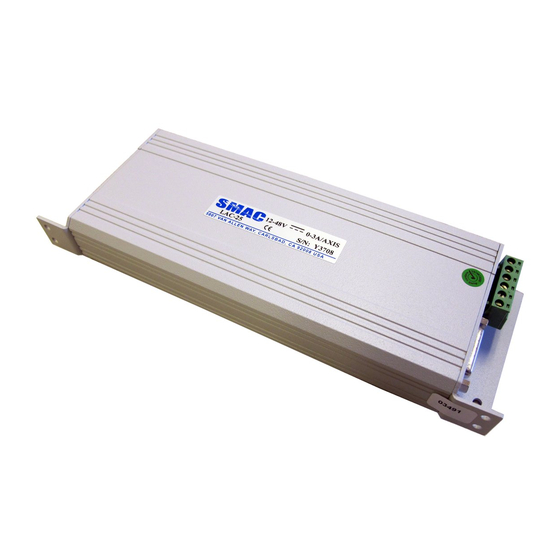
Page 80: Appendix 2 Outline Drawing
SMAC LAC-26 Technical Reference Manual Appendix 2 Outline drawing 4/29/2013... - Page 81 SMAC LAC-26 Technical Reference Manual 4/29/2013...
-
Page 82: Aooendix 3. Connector Pin Definitions
SMAC LAC-26 Technical Reference Manual Aooendix 3. Connector Pin Definitions J2 - Power Interface J3 – Axis 2 Motor Output 8-Pin 5.08mm Centers Phoenix 4-Pin 5.08 Centers Phoenix Digi-Key# ED1721-ND Digi-Key # ED1719-ND 1. Axis 1 Motor- output 1.Motor Phase A 2. -
Page 83: Appendix 4 - Summary Of Lac-26 Commands
SMAC LAC-26 Technical Reference Manual Appendix 4 – Summary of LAC-26 Commands 4/29/2013... -
Page 84: Appendix 5 Amc Driver Troubleshooting
SMAC LAC-26 Technical Reference Manual Appendix 5 AMC Driver Troubleshooting B.1 Fault Conditions and Symptoms An inoperative drive is typically an indication of a disabling fault condition. The fault condition can either be caused by a system parameter in excess of software or hardware limits, or by an event that has been user- configured to disable the drive upon occurrence. - Page 85 SMAC LAC-26 Technical Reference Manual For example, the motor velocity can be limited by giving a value to the Motor Over Speed selection in DriveWare. An "event action", such as "Disable the Power Bridge", can also be assigned for DriveWare to take if the motor reaches this speed.
- Page 86 SMAC LAC-26 Technical Reference Manual B.1.5 Motor Problems A motor run-away condition is when the motor spins rapidly with no control from the command input. The most likely cause of this error comes from having the feedback element connected for positive feedback.
- Page 87 SMAC LAC-26 Technical Reference Manual Send Ind.Off Data This example shows the data written to index 105 (69h) as 0FFC. The drive previously had a value of 0FDC. Bit 5 was enabled to activate the Phase Detection Fault Bit in the reset event action index.
Need help?
Do you have a question about the LAC-26 and is the answer not in the manual?
Questions and answers