Table of Contents
Advertisement
Quick Links
2.4GHz 6-CHANNEL
COMPUTER RADIO
INSTRUCTION MANUAL
Tactic' c'
Tactic's TTX660 computer transmitter uses
the advanced 2.4GHz spread spectrum
the a
SLT "Secure Link Technology" protocol for
SLT "
solid
solid, interference-free control of R/C
models. Ball-bearing gimbals, a wireless
mod
trainer system, 30 model memories, and
train
advanced programming options are just
adv
a few of the benefits which can be used
a fe
on
on models of all sizes. Tactic 2.4GHz
tran
transmitters are compatible only with
Tactic brand receivers and those utiliz-
Tac
ing the SLT protocol.
ing
For safe operation and
best results, it's
strongly recommended
to read this manual in
its entirety before use! Also read
its en
and understand the instructions
and u
included with the model. Damage
includ
resulting from misuse or
resulti
modification will void your warranty.
modific
TM
™
Advertisement
Table of Contents

Related Manuals for Hobbico Tactic TTX660

Summary of Contents for Hobbico Tactic TTX660
- Page 1 2.4GHz 6-CHANNEL COMPUTER RADIO INSTRUCTION MANUAL Tactic’s TTX660 computer transmitter uses Tactic’ c’ the advanced 2.4GHz spread spectrum the a SLT “Secure Link Technology” protocol for SLT “ solid, interference-free control of R/C solid models. Ball-bearing gimbals, a wireless trainer system, 30 model memories, and train advanced programming options are just a few of the benefits which can be used...
-
Page 2: Table Of Contents
TABLE OF CONTENTS SLT TECHNOLOGY, Tx-R, AND COMPATIBLE RECEIVERS ....5 RECEIVER INSTALLATION ..........5 TTX660 POWER SYSTEM . - Page 3 Aileron Differential ..........23 Aileron Mixer .
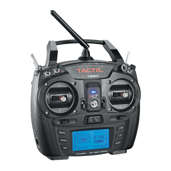
- Page 4 Carrying Handle Antenna Switch B Switch H Switch F Dial Switch E Switch D Switch A Neck Strap Eyelet LED Power Indicator Trim Levers Pushbuttons Firmware Power Upgrade Switch Jack Charge Jack Firmware Upgrade Jack Charge Jack...
-
Page 5: Slt Technology, Tx-R, And Compatible Receivers
SLT TECHNOLOGY, Tx-R, AND COMPATIBLE RECEIVERS Tactic’s custom SLT technology ensures that transmitters emit a strong, clear, frequency- hopping 2.4GHz signal, and that your compatible receiver accepts no signal except yours. Binding Tactic brand receivers is as simple as pushing a button, which creates a locked-in, interference free link. -
Page 6: Charge Jack And Rechargeable Batteries
of the wires before disconnecting the plug from the Tx. Install the NiCd or NiMH battery by fi rst inserting its connector into the jack in the battery compartment. Battery voltage is shown on the LCD’s home screen for easy monitoring. A “LOW BATTERY”... -
Page 7: Gimbal Sticks
channels, applying differential reduction to a channel, etc.). Some electronic functions can be turned on/off by the pilot during fl ight such as a timer. Other functions should only be altered while the model is on the ground, such as changing travel limits or reversing for a particular channel. -
Page 8: Digital Stick Trims
Stick Tension: Silver screws on the back of each gimbal are used to adjust the stick tension, as shown at left. Turn the screw clockwise to make stick tension more fi rm. Turn the screw counter-clockwise to make stick tension more light. Throttle Ratchet: A silver ratchet bar is mounted across the throttle gimbal. -
Page 9: Home Screen
HOME SCREEN 5.3V The factory default screen and menus will be for airplanes. >NAME See the next section for navigating and changing menus for model type and other functions. O OO 1. Memory Number 5. Timer RF-ON 2. Model Name 6. -
Page 10: Lcd And Programming Controls, Menu Navigation
LCD, PROGRAMMING CONTROLS, MENU NAVIGATION The LCD contrast and brightness is adjustable for optimum viewing. Six pushbuttons navigate the menus and settings. Single button pushes will result in a single incremental adjustment on-screen. Holding a button for a short time will result in slow scrolling of adjustments;... -
Page 11: System Setup
SYSTEM SETUP SYSTEM SETUP USER NAME : TACTIC Fundamental settings for the transmitter are located in this STICK MODE: MODE2 menu. With the power switch in the OFF position, press and hold ENTER, turn the power switch ON and wait for the CONTRAST SYSTEM SETUP screen to show. -
Page 12: Contrast
Unscrew the left gimbal assembly and lift it out of the transmitter case. Slide the elevator arm onto the mounting pin in the left gimbal in the same way you removed it from the right gimbal. NOTE: As you can see, the two gimbals are identical but installed in the transmitter 180 degrees opposite each other. -
Page 13: Model Setup Menu - Airplanes
MODEL SETUP MENU – AIRPLANES From the home screen, press and hold ENTER for 2 seconds MODEL SETUP to fi nd the MODEL SETUP menu which is for setting of MODEL SELECT fundamental operating parameters as shown here. MODEL MANAGEMENT WING TYPE CHANNEL ASSIGNMENTS WARNINGS... - Page 14 Copy: To copy all parameters from one model memory to another, place the cursor over “Copy” and press ENTER. The “COPY FROM” page will show. Highlight the memory to copy FROM and press ENTER. Now the “COPY TO” page will show. GeeBee GeeBee Axe 1 00...
-
Page 15: Wing Type
WING TYPE This is for setting the type of tail and wing confi guration for the model. Depending on the mixes used and setup of the aircraft, it might be necessary to change the aileron, elevator, or rudder reversing settings to achieve the proper throw FLAP 1 A I directions for the model. - Page 16 Airplane - V-tail 1AIL/ 2AIL/ 1AIL 1FLAP 2AIL 1FLAP V-TAIL1 V-TAIL1 V-TAIL1 V-TAIL1 THRO THRO THRO THRO V-TAIL2 V-TAIL2 V-TAIL2 V-TAIL2 Left Rudder Right Rudder Up Elevator AUX1 FLAP AUX1 FLAP AUX2 AUX2 AIL2 AIL2 V-tail: Elevator and rudder channels are mixed. Two servos are used in the tail – one for each control surface, with connections as shown in the graphic above.
-
Page 17: Channel Assignments
CHANNEL ASSIGNMENTS This function allows transmitter channels to be re-assigned to different channels before being sent to the receiver. This can be useful for models having unusual confi gurations or inaccessible receivers. Some small electric fl ight models use only elevator, throttle, CHANNEL ASS I GNMENTS and rudder channels (not aileron). -
Page 18: Trainer
TRAINER TRAINER The process of linking transmitters for training purposes is explained on page 37. When in training mode with the TTX660 being used by the teacher, this radio can allow the teacher to transfer control of all or only certain channels to the student if desired. -
Page 19: Dual-Rates And Exponential
Sub-trim: Finely adjusts a channel’s center position. Be SERVO SET: Sub Tri m aware that extreme adjustments of sub-trim could possibly result in servo binding if the servo’s output arm moves too far in the model. This is available for all channels. Travel limits: Sets the maximum travel limits for each channel. -
Page 20: Ch5 And Ch6 Set
Moving the control stick for the channel shown on-screen will change the position of the vertical line in the graph. The point where the vertical line intersects the diagonal line is shown at the bottom-left on the screen. The “x” (horizontal) coordinate is on the left, and “y”... -
Page 21: Throttle Curve
Travel: To adjust the travel limits for a selected channel, defl ect the switch to one position and adjust the maximum travel limit for this switch position, and then repeat for the opposite switch position. Highlight either and press CLEAR to change back to the default setting. -
Page 22: Throttle Cut
Pressing will adjust the vertical position of curve THROTTLE CURVE at this exact point. Adjust as desired. Point RA TE: +52% CTRL:----- THROTTLE CURVE EXPO: Point + 1 5% > +52% RA TE: +48% CTRL: SD(0) Repeat these steps to set points 2, 3, EXPO: and 4 on the graph as desired. -
Page 23: Aileron Differential
The throttle cut function will only work when the throttle THROTTLE CUT stick position is below the trig point. To set this point, move the cursor next to TRIG but do not press ENTER. Move CTRL the throttle stick to the desired position that will trigger the throttle channel to move to the cutoff position. -
Page 24: Aileron Mixer
Normal Switch Control AILE D IFFERENTIAL AILE D IFFERENTIAL Aile Aile NORM: SP. 0: SP. 1: SP. 2: CTRL: _____ CTRL: SC(2) Normal: To make AILE DIFFERENTIAL active at all times do NOT assign a switch at the CTRL line. Press ENTER to highlight the differential rate percent and press to fi nd the desired value. -
Page 25: Rudder Mixer
RUDDER MIXING Mixing the rudder channel to the aileron and/or elevator channels can be very useful for trimming an airplane to be neutral when using the rudder. Normal Switch Control RUDD- >AILE MIXING RUDD- >AILE MIXING Aile Elev Ail e El ev NORM: SP. -
Page 26: Air Brake Set
Normal Switch Control FLAP- >ELEV MIXING FLAP- >ELEV MIXING Elev Fl ap El ev Fl ap NORM: SP. 0: SP. 1: SP. 2: CTRL: ----- CTRL: SC (2 ) 1AI1FL: Highlight the FLAP ELEV mix percent and adjust as desired. Press ENTER when fi nished. -
Page 27: Programmable Mixer
A I R BRAKE SET ELEV: When the 2AI wing type is selected the brake can be mixed to elevator and/or aileron. Adjust each mix percentage as AILE: needed. Select a switch to turn the mix on/off. CTRL: SE A I R BRAKE SET ELEV: When the 2AIL1FL wing type is AILE:... -
Page 28: Rf Output
RF OUTPUT The RF output signal can be turned on or off. If changing any RF OUTPUT programming parameters in the radio it’s recommended to turn the RF off to conserve radio power. Leave the RF output RF ON/OFF: ON signal ON anytime the model is being controlled. -
Page 29: Model Setup Menu - Helicopters
The “START/STOP” screen should show. Moving the stick T imer up or down will show changes to the “THROTTLE” position value. The “START/STOP” value shows the trip point where START /STOP: +42% starting and stopping the timer will occur. THROTTLE : +42% Move the stick to the desired position for the timer’s trip point and press ENTER. -
Page 30: Settings Menu - Helicopters
SWASH TYPE 1 Servo: Tilting of the swash plate is accomplished with one servo for control of the elevator axis and one servo for the aileron axis. Another servo directly controls collective 1 Servo pitch. Selecting this swash type means that no swash plate mixers are required or used. -
Page 31: Throttle Cut
if using a helicopter which has CCPM mixing, read the SWASH TYPE section on the previous page before adjusting the reversing and travel limits settings. THROTTLE CUT Allows the throttle channel’s output to be quickly moved to a user-defi ned position by fl ipping a switch. -
Page 32: Throttle Curve
To select a switch to turn throttle hold on or off during fl ight, set the Control fi eld to ON. With the cursor next to CTRL, defl ect the switch that will control throttle hold. In one position the control will be ON. Moving the switch to the opposition will turn the control OFF. Move the cursor next to “Position”... -
Page 33: Pitch Curve
To set points on the curve, start at the minimum throttle THROTTLE CURVE position which will be noted as point “L”. A point for “L” is Point not marked on the graph, but is the left-most end of the curve line. -
Page 34: Gyro Mixing
GYRO MIXER This function is for setting and adjusting the sensitivity of an optional tail gyro. Enter this screen. Normal Switch Control GYRO MIXING GYRO MIXING SP. 0: NORM: SP. 1: SP. 2: CTRL: ----- CTRL: SE(2) To make the gyro mixing active at all times do NOT assign a switch at the CTRL line. Press ENTER to highlight the normal mixing rate, and press to fi nd the desired value. -
Page 35: Throttle Mixing
THROTTLE MIXER This mix is used for non-heading hold gyros or when a heading hold gyro is in normal mode. The helicopter’s throttle channel can be mixed to the tail (rudder) channel. This mix can remain active at all times, or be controlled by selecting a switch on the CTRL line. -
Page 36: Programmable Mixer, Rf Output And Timer
SWASH R I NG SWASH R I NG RA TE: 1 50% RA TE: ELEV: ELEV: AILE: AILE: Once inside this function, press SWASH R I NG ENTER to highlight the “Rate” value. Press to fi nd the RA TE: desired maximum rate. -
Page 37: Failsafe Function
4. Release the “LINK” or “BIND” button. 5. If the linking is successful, the Rx LED will fl ash once and then remain ON. 6. Test for proper Tx/Rx functionality before use. If the radio doesn’t appear to have become properly linked, repeat steps 1–6 above and move the Tx at least three feet away from the Rx. - Page 38 OFF position. This will terminate the wireless link between both transmitters. Teacher’s radio: Tactic TTX410/610 Student’s radio: Tactic TTX660 1. Link the teacher’s TTX410/610 to the Rx. Remove power from the model, and then turn the teacher’s Tx off.
-
Page 39: Range Test
3. Move the student’s transmitter to within 3 feet of the teacher’s transmitter, turn the power switch on and set the RF OUTPUT to ON. 4. The TTX410/610 LED should fl ash three times and then stay on to indicate the bind was complete. -
Page 40: Warning Indications
3. Move the cursor over “99sec”. This time determines how long before the radio’s output power automatically returns to full power. 4. Place the Rx/model on the ground and apply power to the Rx/model. 5. Hold the Tx as it will be held during fl ight and press ENTER. The range test timer on-screen will start to count down. -
Page 41: Flying The Aircraft
easily becoming dislodged during normal fl ight. It’s best to check the system with the propeller removed from the aircraft. 1. Once all connections are made, check the general operation of the radio and all other components before attempting a fl ight. 2. -
Page 42: Important Warnings And Precautions
4. During the fi rst fl ight, it might be necessary to re-trim the main channels to allow the model to sustain smooth, even fl ight. If further adjustments are required on the ground, make sure to turn off the engine or ESC/motor beforehand. 5. -
Page 43: Ttx660 Specifications
TTX660 SPECIFICATIONS Model types: airplane, helicopter, drone Channels: 6 Frequencies: 2.403 – 2.480GHz Protocol: Tactic SLT Modulation: FHSS spread spectrum Input power: 3.40 - 7.00V DC, four 1.5V alkaline or 1.2V NiCd/NiMH “AA” single cells. Jack included for connecting optional 4.8V NiCd or NiMH pack Current consumption: approx. -
Page 44: Safety Guide
Practice good safety precautions at all times when fl ying model aircraft. The AMA can assist in locating authorized local fl ying clubs and fi elds. The Tactic TTX660 transmitter is intended for use with radio control model hobby airplanes and helicopters. Use with non-hobby related products for non-hobby related activities is not recommended or encouraged. -
Page 45: Fcc Statement
Declaration of Conformity: Product: Tactic TTX660 2.4GHz 6-Channel Tx Item number: TACJ2660 Device class: 1 The objects of the declaration described here are in conformity with the requirements of... - Page 46 E-mail: hobbyservices@hobbico.com Champaign, IL 61822 Entire contents © 2017, Hobbico., Inc. Made in China TACJ2660 This product is suitable only for people of 14 years and older. This is not a toy! WARNING: CHOKING HAZARD - May contain small parts. Keep away from children under 3 years.
- Page 48 ® © 2017 Tactic A Hobbico company. TACJ2660...
Need help?
Do you have a question about the Tactic TTX660 and is the answer not in the manual?
Questions and answers