Table of Contents
Advertisement
Quick Links
Advertisement
Table of Contents

Subscribe to Our Youtube Channel
Related Manuals for TEL AFA4000/2

Summary of Contents for TEL AFA4000/2
- Page 1 AFA4000/2 Airflow monitor Installation and operating manual Issue 1...
-
Page 2: Table Of Contents
Overview: Auto Sash Controller ........................31 Features ................................31 Auto Sash control options ........................32 Control system components........................35 Installation: Airflow Monitor ..........................43 Location ................................43 Installation ..............................45 Connections ..............................48 Dimensions ..............................52 AFA4000/2 Airflow Monitor / p.2... - Page 3 6.10 Auto Sash System Control Box - general wiring diagram ............90 6.11 Start up ................................91 Calibration ................................. 92 AFA4000/2 Airflow Monitor ........................92 Auto Sash Controller 1, 2 or 3 position....................95 Sash lock function ............................96 Auto Sash Controller –...
- Page 4 Cleaning and maintenance ..........................161 14.1 Cleaning ............................... 161 14.2 Contamination ............................162 14.3 Maintenance .............................. 162 Technical specifications ............................. 163 15.1 AFA4000/2 Airflow Monitor ......................... 163 15.2 Auto Sash Controller ..........................165 Warranty .................................. 171 Index ..................................173 AFA4000/2...
-
Page 5: Introduction
1. Introduction The TEL AFA4000 is a system for controlling and monitoring airflow in industrial and educational fume cupboards and biological safety cabinets for user safety. The AFA4000 airflow monitor and controller is available with optional Auto Sash integration. Using the Auto Sash with the AFA4000 controller means you will no longer need a separate Auto Sash keypad. -
Page 6: Features
• Visual & audible alarms • Three digital inputs and three digital outputs • Diagnostics Menu • Bespoke overlay designs, with a choice of two, coloured cases • Bespoke software options tailored to customer requirements • Touch sensitive buttons AFA4000/2 Airflow Monitor / p.6... -
Page 7: Safety
WARNINGS appear as follows: Switch off the mains voltage and remove the mains cord before maintenance. Always follow the instructions given by warning labels on the equipment. For further information refer to this guide and other documentation provided. AFA4000/2 Airflow Monitor / p.7... -
Page 8: Operating Conditions
• Relative humidity below 80% for temperatures up to 31°C, decreasing linearly to 50% at 40°C • Electrical supply fluctuations not to exceed +10% of nominal voltage The protection provided by the equipment may be impaired if the environmental conditions do not lie within these parameters. AFA4000/2 Airflow Monitor / p.8... -
Page 9: Electrical Safety
• Disconnect the equipment from live voltage sources before adjustments, replacements, maintenance or repairs are carried out. If the equipment must be operated during adjustment, maintenance or repair, only a supplier’s Service Engineer is to carry out the procedure. AFA4000/2 Airflow Monitor / p.9... -
Page 10: Electrical Protection
External circuits: External circuits which are connected to the Auto Sash controller, except mains connection, shall be insulated by double or reinforced insulation from the mains. AFA4000/2 Airflow Monitor / p.10... -
Page 11: Emc Compliance
The Airflow Monitor System and Auto Sash Controller Systems are classified as digital devices used exclusively as industrial, commercial or medical test equipment. They are exempt from the technical standards specified in Part 15 of the FCC Rules and Regulations based on Section 15.103 (c). AFA4000/2 Airflow Monitor / p.11... -
Page 12: Overview: Airflow Monitor
To access and or change the password contact the supplier for the engineer’s password and enter the passwords in the Main Menu, or alternatively use a laptop connected to the Com port and use the Upload/Download software provided. AFA4000/2 Airflow Monitor / p.12... - Page 13 • The display backlight dims to save energy when the following functions are in use: • Fan Off activated- display backlight dims until Fan On is selected. Backlight brightens to normal level when you access the Set Up or Diagnostics menus. AFA4000/2 Airflow Monitor / p.13...
-
Page 14: Alarms And Events
Fan is switched off. The display backlight will dim when in a Fan off condition. Start Up Pushbutton I is set to Fan On/Off, the start-up timer is enabled from 0 - 600 seconds when the Fan is switched on. The remaining start up time is displayed. AFA4000/2 Airflow Monitor / p.14... - Page 15 Fire Alarm The Fire alarm input is activated. Fire alarm alternates on/off with the velocity reading. High Air This alarm displays when the airflow is more than the High Air cut off value. AFA4000/2 Airflow Monitor / p.15...
-
Page 16: Controls And Indicators
3.3.2 Audible alarm sounder The AFA4000/2 has an audible sounder with local or remote mute facilities. You can permanently disable the alarm in the Cal Config Menu. The audible alarm is muted when Fan Off is selected on pushbutton I or when the Setback or Alarm Disable functions are activated. - Page 17 Press Mute for 5 seconds to access the calibration and configuration menus. ↑ / ↓ Use the ↑ ↓ buttons to scroll through the calibration and configuration menus or to select options and values. AFA4000/2 Airflow Monitor / p.17...
-
Page 18: Operator Display Panel Menu Navigation
Passwords * Monitor passwords menu Select the password to set: • Admin • Calibration • Configure Enter and re-enter the new password, then press the Mute button. Select Done to return to the Main menu. AFA4000/2 Airflow Monitor / p.18... - Page 19 Auto Sash Configuration menu Note: This option is only available if the Auto Sash is connected. Menu item Option Instructions Shows the firmware (F/W) TEL Sash Closer Read-only information and Hardware (H/W) versions Setup Menu * Auto Sash setup menu See section 8.2.1.
-
Page 20: External Connections
External connections 3.5.1 Inputs The AFA4000/2 has the following inputs: 3.5.1.1 Input 1, Input2, Input 3 These are volt-free inputs configurable for: • Normally closed relays • Normally open relays or • Analogue 0 - 5 Vdc input The inputs can be configured as:... - Page 21 3.5.5.2 PIR occupancy sensor Auxiliary PIR used for close sash alarm based on the fume cupboard occupancy. 3.5.5.3 Mains fail battery unit Auxiliary plug-in battery unit has a mains fail alarm. AFA4000/2 Airflow Monitor / p.21...
-
Page 22: Functions
Functions 3.6.1 Airflow functions The AFA4000/2 airflow display can be set up using the pushbutton menus to display airflow in units of m/sec or fpm and can also be set to show plain text Air Safe & Air Fail only. - Page 23 Each Pushbutton has a Power Up Memory function. The Power Up Memory function sets the pushbutton back to its last status, following a power fail cycle. For example, when the Fan is On during a power failure, the AFA4000/2 powers up with the Fan pushbutton set to On.
- Page 24 • Pushbutton III set to Gas On / Off • Gas On / Off Relay operates Sockets On / Off • Pushbutton III set to Sockets On / Off • Sockets On / Off Relay operates AFA4000/2 Airflow Monitor / p.24...
- Page 25 • Pushbutton III set to Emergency On / Off • Emergency On /Off Relay operates 3.6.4 Input functions The AFA4000/2 has 3 programmable inputs that can be set to: • Analogue (0 - 5 Vdc) • Digital open or • Digital closed operation 3.6.4.1...
- Page 26 • Emergency toggles on /off with display – (when configured) • Audible alarm sounds. Can be muted by pressing the Mute pushbutton • Emergency alarm relay operates (when configured) Sash High When input configured as Sash High is activated: AFA4000/2 Airflow Monitor / p.26...
- Page 27 • Audible alarm sounds • Audible can be muted by pressing the Mute pushbutton. This silences the alarm (when configured) Fan Stop When the input configured as Fan Stop is activated: • Off is displayed AFA4000/2 Airflow Monitor / p.27...
- Page 28 When the input configured as Fire Alarm is activated: • Red Alarm Halo illuminated • Fire Alarm is displayed • Audible alarm sounds Note: Audible can be muted by pressing the Mute pushbutton. This silences the alarm (when configured) AFA4000/2 Airflow Monitor / p.28...
-
Page 29: Components
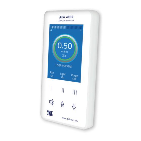
Components 3.7.1 Airflow monitor components • 1 – AFA4000/2 Airflow Monitor • 1 – Airflow Sensor c/w 2 metre RJ45 Sensor Cable • 1 – Plug in type low voltage power supply with 5 metre Cable Figure 2: AFA4000/2 airflow monitor AFA4000/2 Airflow Monitor / p.29... - Page 30 3.7.2 Auxiliary components The following auxiliary components are available for the AFA4000/2 airflow monitor: Component Function Sash High Proximity Switch Used for Sash High Alarm Sash High Micro Switch Used for Sash High Alarm Personnel Sensor Passive Infra-Red sensor - used for Close Sash Alarm...
-
Page 31: Overview: Auto Sash Controller
The sash automatically closes when a signal is received System (BMS) Inputs from the BMS. • Building Management The Auto Sash Controller sends signals to the BMS System (BMS) Outputs regarding the current status of the fume hood. AFA4000/2 Airflow Monitor / p.31... -
Page 32: Auto Sash Control Options
• When the Tiptronic feature is enabled, manually tip the sash upwards and the sash will drive to the mid- position. • Manually tip the sash downwards and the sash will drive to the bottom position. AFA4000/2 Airflow Monitor / p.32... - Page 33 Lock position has been calibrated, the Auto Close feature is disabled and the sash locks in its current position when the sash is raised to the Sash Lock position or higher. This facilitates loading the Fume Cupboard. AFA4000/2 Airflow Monitor / p.33...
- Page 34 4.2.2 Auto Sash Controller with Sash Low micro-switch A Sash Low Micro-Switch can be specified for fitting by TEL or by the fume hood manufacturer. The switch can be arranged to be open / closed when the sash is closed, depending on fitting.
-
Page 35: Control System Components
Control system components The Auto Sash Control System comprises of a control unit and additional components. Figure 3: Typical location of main components Note: This example installation is fitted with a pulley and wire sash drive. AFA4000/2 Airflow Monitor / p.35... - Page 36 The Auto Sash Control Unit processes inputs from sensors, switches associated with the sash control function and output signals relevant to the motor drive(s) and the alarm panel. Figure 4: Auto Sash Control Unit - single and dual controller enclosure AFA4000/2 Airflow Monitor / p.36...
- Page 37 'ignored' by the sensor. When the user is not present at the fume hood, the sash will close automatically. This follows a pre-set delay time, if the Sash Light Curtain is not broken and the sash is open. AFA4000/2 Airflow Monitor / p.37...
- Page 38 • The infra-red transmitter has multiple, closely spaced, Light Emitting Diodes (LEDs) to facilitate the detection of small objects. AFA4000/2 Airflow Monitor / p.38...
- Page 39 A sensor on one side of the fume hood detects the reflection of a beam of light from a self-adhesive strip of retro-reflective tape mounted on the opposite inside wall of the fume hood. AFA4000/2 Airflow Monitor / p.39...
- Page 40 During the initial on-screen calibration set up the sash controller detects the sensor direction of travel and then provides position information of the sash to the Auto Sash Control Unit, to enable calibration of the sash open / closed positions. AFA4000/2 Airflow Monitor / p.40...
- Page 41 The Tilt Switch is an optional, third party supplied component, which is fitted to the fume hood top panel. It operates to isolate the Auto Sash controls, when the top panel is open to facilitate the servicing of the fume hood. Figure 13: Typical third-party tilt switch AFA4000/2 Airflow Monitor / p.41...
- Page 42 Three types of drive are available, none of which preclude manual opening / closing: • Rack and pinion drive • Chain and sprocket drive • Pulley and wire drive Chain and sprocket drive Rack and pinion drive Pulley and wire drive Figure 15: Example drives AFA4000/2 Airflow Monitor / p.42...
-
Page 43: Installation: Airflow Monitor
• The standard 2 metre ‘telephone style’ sensor cable must reach from the back of the AFA4000/2 airflow monitor to the airflow sensor. When possible ensure that the airflow sensor is mounted on the same side of the fume cupboard as the AFA4000/2. Note: Longer sensor cables are available on request. - Page 44 If possible, mount the sensor on the front of the fume cupboard and use a short length of tube. Tube lengths of more than 1 m or smaller diameter will restrict the AFA4000/2 Airflow Monitor / p.44...
-
Page 45: Installation
5.2.1 AFA4000/2 Use the cut-out details provided with the unit (Figure 17) to cut-out and drill the holes in the fume cupboard for the AFA4000/2 mounting bracket. Make sure that the AFA4000 fits into the cut-out before proceeding. AFA4000/2 Airflow Monitor / p.45... - Page 46 Figure 17: AFA4000 cut-out template Note: Print to A4. Do not scale or print to fit page. Note: Separate mounting boxes and adaptor plates are available for retro-fitting to older fume cupboards. AFA4000/2 Airflow Monitor / p.46...
- Page 47 Push the bottom of the AFA4000 onto the mounting bracket (D in Figure 18). Secure the AFA4000 to the mounting bracket using the fixing screw in the bottom face of the monitor (E in Figure 18). AFA4000/2 Airflow Monitor / p.47...
-
Page 48: Connections
Note: Print to A4. Do not scale or print to fit page. Connections Connect the power supply cable into the back of the AFA4000/2 (H in Figure 20) and to the connection on top of the fume cupboard. Connect the ‘telephone style’ airflow sensor plug-in cable to the sensor and the back of the AFA4000/2 unit (J in Figure 20). - Page 49 Figure 20: AFA4000/2 and AFA4000/2/AS monitor connections 0-10 V velocity re-transmission Relay output 3 (used if relay interface output, 0-10 Vdc over 0-1.00 m/sec / is not fitted) 0-200 fpm Input 1 – digital or analogue 15 Vdc power supply (used if relay interface is not fitted) Input 2 –...
- Page 50 Figure 21: AFA4000/2 typical connection diagram AFA4000/2 Airflow Monitor / p.50...
- Page 51 Figure 22: AFA4000/2/AS typical connection diagram AFA4000/2 Airflow Monitor / p.51...
-
Page 52: Dimensions
Dimensions Figure 23: : AFA4000/2 and AFA4000/2/AS dimensions AFA4000/2 Airflow Monitor / p.52... - Page 53 Figure 24: SM7 airflow sensor dimensions AFA4000/2 Airflow Monitor / p.53...
-
Page 54: Start Up
Start up 5.5.1 AFA4000/2 The AFA4000/2 must be field-calibrated once the room air supply and exhaust is proportionally balanced. When the unit is powered up, the following sequence of events occurs: The alarm performs a self-test of its functions and audible alarm which takes approximately 3 seconds. - Page 55 • When the Auto Sash Controller is disconnected, the Auto sash controller status and menus are not displayed. AFA4000/2 Airflow Monitor / p.55...
-
Page 56: Installation: Auto Sash Controller
Note: For horizontal mounting, the control box should always be mounted with the lid / front panel facing upwards. • Screwed to the outside wall of fume hood wall - vertical mounting Figure 25: Auto Sash Control Unit Lid/Front Figure 26: Rear of Auto Sash Control Unit Panel AFA4000/2 Airflow Monitor / p.56... - Page 57 / or sidewall. Where a cable is supplied with a DIN connector, the grommet should have a minimum internal diameter of 17mm (0.67"). • Do not overstress cables by bending, for example when passing at 90° through a sidewall. AFA4000/2 Airflow Monitor / p.57...
- Page 58 Figure 28: Sash Control System – general layout, wiring schematic and illustration (inset) AFA4000/2 Airflow Monitor / p.58...
-
Page 59: Auto Sash Keypad / Alarm Panel
Fit the Auto Sash Keypad to the fume hood using either a single gang socket for UK applications (Figure 29) or using a cut-out to the (Version 2) dimensions (Figure 30). Figure 29: Version 1 - UK Single Gang Keypad Fits in Standard Single Gang Socket AFA4000/2 Airflow Monitor / p.59... -
Page 60: Auto Sash Motor Drive Unit
A Motor Drive Unit is used to automatically raise and lower the fume hood sash. Three types of drives are available: • Rack and pinion motor drive. • Chain and sprocket motor drive. • Wire and pulley motor drive. The optimal choice of sash drive type depends on whether: AFA4000/2 Airflow Monitor / p.60... - Page 61 To ensure that the T-bar fixing clears the bottom of the motor assembly, there should be at least 50 mm between the top of the sash and the bottom of the motor drive assembly, when the sash is fully opened. AFA4000/2 Airflow Monitor / p.61...
- Page 62 Ensure that the rack is free to move over the full sash opening before marking up and fixing the T-bar to the sash frame. Note: The rack must to run vertically at 90º to the horizontal axis of the sash frame. AFA4000/2 Airflow Monitor / p.62...
- Page 63 See the wiring schematic in section 6.10 and Figure 31. Note: It is important to observe the correct polarity when making electrical connections. Connect the clutch assembly to the Auto Sash Control Unit using the cables provided (with blue and yellow connectors). AFA4000/2 Airflow Monitor / p.63...
- Page 64 Figure 34: Side views of a rack and pinion drive typical installation AFA4000/2 Airflow Monitor / p.64...
- Page 65 Fit the taper bore sprocket to the shaft and ensure that the sprocket is securely fitted. Where possible positioned the motor drive and sprocket centrally on the shaft. The motor assembly should be fitted to a rigid framework to support the motor. AFA4000/2 Airflow Monitor / p.65...
- Page 66 Fit the motor so that the drive sprocket is in line with the counterweight pulley. Fit one end of the chain to the counterweight or sash wire near to the counterweight. Fit the freewheeling sprocket in line with the drive sprocket. AFA4000/2 Airflow Monitor / p.66...
- Page 67 Fit the motor assembly so that the guide pulleys are in line with the sash wire. Run the sash wire over the first guide pulley, around the drive pulley and then over the final guide pulley. AFA4000/2 Airflow Monitor / p.67...
-
Page 68: Sash Light Curtain
Figure 38: Sash Light Curtain Control Box Use the pre-assembled cables and connectors supplied to connect the Light Curtain Control Box to the Auto Sash Control Unit. See the wiring schematic in section 6.10 and Figure 31. AFA4000/2 Airflow Monitor / p.68... - Page 69 The sash light curtain transmitter and receiver should be fitted so that their cable entry / exit points are at the top. Ensure that the light beam path is free from other obstructions. AFA4000/2 Airflow Monitor / p.69...
- Page 70 0 to 3 m (0 to 118.11") range of fume hood widths. For a typical fume hood width of 1 to 2 m (39.37 to 78.740"), the maximum allowable misalignment / displacement ranges from approximately 20 to 40 mm (0.79 to 1.58"). AFA4000/2 Airflow Monitor / p.70...
- Page 71 Note: There is a 123 mm (4.84") gap from the top of the light curtain transmitter to the first LED down and a 22 mm (0.87") gap from the bottom of the transmitter to the first LED up. AFA4000/2 Airflow Monitor / p.71...
- Page 72 Drill the holes for the fixing screws. Use the 2 mm (0.08") drill bit provided and fix the transmitter and receiver. Figure 43: Transmitter / Receiver fixing holes AFA4000/2 Airflow Monitor / p.72...
- Page 73 Pass the cables through the sidewall and connect to the Sash Light Curtain Control Box on the top of the fume hood. Connect the light curtain transmitter and receiver to the Sash Light Curtain Control Box using the plug-in RJ45 cables provided. AFA4000/2 Airflow Monitor / p.73...
- Page 74 Control Box to the Auto Sash Control Unit. See the wiring schematic in section 6.10 and Figure 31. Fix the light curtain transmitter and receiver to the sidewall using their fixing holes and re-attach the plastic covers. AFA4000/2 Airflow Monitor / p.74...
-
Page 75: Installing And Aligning The Under Sash Sensor
Attach the 5 m cable to the sash counterweight to keep the cable taught as the sash opens or closes. Encase the cable from the sash counterweight to the sash controller box can in plastic sheathing to guide the cable slack and stop it from snagging. AFA4000/2 Airflow Monitor / p.75... - Page 76 Position the centre of the retro-reflective tape strip in line with the centre of the sensor. A small offset between the sensor and retro-reflective tape strip is acceptable. The maximum offset values are shown in Figure 49. AFA4000/2 Airflow Monitor / p.76...
-
Page 77: Tilt Switch
6.10 and Figure 31. • Link out / connect the relevant terminals on the Auto Sash Control Unit when not using a Tilt Switch. See the wiring schematic in section 6.10 and Figure 31. AFA4000/2 Airflow Monitor / p.77... -
Page 78: Sash Low Switch
Auto Sash Control Unit to terminals C and NO on the switch. If the switch is installed so that the lever pushes in when the sash is open, connect the wiring to the Auto Sash Control Unit to terminals C and NC on the switch. AFA4000/2 Airflow Monitor / p.78... - Page 79 Connect the Sash Low Proximity Switch to the Auto Sash Control Unit (Figure 52). See the wiring schematic in section 6.10 and Figure 31. Figure 52: Sash low proximity switch wiring schedule AFA4000/2 Airflow Monitor / p.79...
-
Page 80: Sash Position Sensor
Where the wire runs at an angle to the sensor, ensure the angle is as small as possible to prevent the wire from rubbing on any part of the sensor body, including the cable housing extension. AFA4000/2 Airflow Monitor / p.80... - Page 81 4.85 mm (0.18") diameter fixing hole in its centre. • The sash cable using a cable tie, ensuring that the fixing ring does not run over the pulleys. • The counterweight using a cable (Figure 55). AFA4000/2 Airflow Monitor / p.81...
-
Page 82: Personnel Sensor
Personnel Sensor. Mount the sensor centrally to the front of the fume hood and above the fume hood sash, use the fixing holes in the back of the sensor. See the table in Figure 56 for the correct mounting hole dimensions and locations. AFA4000/2 Airflow Monitor / p.82... - Page 83 The Personnel Sensor should be positioned so that it points straight down, with the horizontal axis of the sensor parallel to the horizontal axis of the fume hood (Figure 57). Note: Do not mount the sensor higher than 250 0mm (98”) from the laboratory floor. AFA4000/2 Airflow Monitor / p.83...
- Page 84 Fit the connection cable to the sensor cable inside the sensor housing. Plug the 4-way terminal block into the Auto Sash Control Unit (Figure 58). See the wiring schematic in section 6.10 and Figure 31. Figure 58: Personnel sensor 4-way terminal block AFA4000/2 Airflow Monitor / p.84...
- Page 85 Figure 59: Personnel sensor beam width adjustment potentiometers Adjust the width of the Personnel Sensor beam using the two potentiometers. This is to achieve the best field coverage in front of the fume hood for the hood's width (Figure 60). AFA4000/2 Airflow Monitor / p.85...
- Page 86 The body of the Personnel Sensor can be tilted from 0° to 5° in three increments to achieve this. AFA4000/2 Airflow Monitor / p.86...
- Page 87 Figure 61: Adjusting the personnel sensor beam angle away from the fume hood AFA4000/2 Airflow Monitor / p.87...
- Page 88 ON/OFF (Figure 62). Note: The timer will reset if any movement is detected during the time period. 3 & 4 Pattern depth Set the distance of the detection field away from the sensor. AFA4000/2 Airflow Monitor / p.88...
- Page 89 Self-Diagnostics Setting switch 8 to 'ON' will start a self-diagnostic test when the sensor is switched on. If the test detects a fault the LED will continually flash red and green. AFA4000/2 Airflow Monitor / p.89...
-
Page 90: Auto Sash System Control Box - General Wiring Diagram
6.10 Auto Sash System Control Box - general wiring diagram AFA4000/2 Airflow Monitor / p.90... -
Page 91: Start Up
• When the controller has not been calibrated, the monitor displays the messages: • Sash drive inhibited, if the tilt switch input is open • Auto Sash Not Configured, if the tilt switch is closed AFA4000/2 Airflow Monitor / p.91... -
Page 92: Calibration
7. Calibration AFA4000/2 Airflow Monitor The airflow monitor must be calibrated when it is first installed, or when required during use. When the unit is powered up the following sequence of events occur: 1. The 12 Vdc power is applied to the airflow sensor and a delay on timer is initiated. - Page 93 0.3m/sec (60fpm). Sensor diff too low The monitor does not detect Check that the sensor hose is any difference in the sensor connected and repeat the output between the 2 calibration. airflow samples. AFA4000/2 Airflow Monitor / p.93...
- Page 94 ‘Air Flow’ condition. • When the airflow display is unstable as a result of environmental turbulence or sensor position, following calibration, adjust the sensitivity of the displayed value using the AFA4000/2 Airflow Monitor / p.94...
-
Page 95: Auto Sash Controller 1, 2 Or 3 Position
From the Run Screen press and hold the Mute button for 5 seconds until the Main Menu is displayed. Use the ↑ / ↓ buttons to select Set Up Auto Sash. The display shows the message TEL SASH CLOSER. Press the Mute button to display the current Hardware and Software version, for example, 1. -
Page 96: Sash Lock Function
5 mm. Sash lock function This section describes the calibration of the Auto Sash Controller from the AFA4000/2/AS. Note: Refer to section 7.4 to calibrate the Auto Sash Controller from the Auto Sash keypad AFA4000/2... - Page 97 Note: When you go from the main menu to the run screen, a note briefly appears saying ‘calibration required’. Use the ↑ / ↓ buttons to select Set Up Auto Sash. The display shows the message TEL SASH CLOSER. Press the Mute button to display the current Hardware and Software version, for example, 1.
-
Page 98: Auto Sash Controller - Stand-Alone
When powering up, the Auto Sash Control Unit performs a self-test of its functions, LEDs and the audible alarm. This self-test takes approximately 3 seconds. During the self-test period, all inputs and outputs are de-activated. AFA4000/2 Airflow Monitor / p.98... - Page 99 Press Cancel to abort Calibration" Move the sash to the middle of the sash opening. Press ↑/↓ buttons to determine which arrow activates sash closing. Press the ↑/↓ button which closes the sash, press Enter. AFA4000/2 Airflow Monitor / p.99...
- Page 100 Enter the Password using the ↑ arrow and Enter button, the factory default is 1 0 0 1. In the Set-Up menu, the controller will display Keypad Tones. Press ↓ button, select Sash 1 Settings and press Enter. The controller will display 1. S1 Enabled. AFA4000/2 Airflow Monitor / p.100...
- Page 101 Auto Sash Control Unit. This activates the Sash Control Alarm after the selected time delay and the reset button must be pressed once the Safety Light Curtain has been calibrated. Remove the cover from the Safety Light Curtain Control Box. AFA4000/2 Airflow Monitor / p.101...
- Page 102 Power up the Auto Sash Control Unit. Check that the Safety Light Curtain Transmitter and Receiver are connected correctly and are operational. The red Power On LED will now be visible on the receiver (Figure 66). AFA4000/2 Airflow Monitor / p.102...
- Page 103 Set sw3 to Off to store the settings. Turn the gain potentiometer approximately 5 degrees clockwise to ensure sufficient gain. Use a glass object to test whether it breaks the beam. Do this across the entire open face of the fume hood. AFA4000/2 Airflow Monitor / p.103...
- Page 104 The sensor will be fully operational approximately 10 seconds after the sensor is powered up. The LED on the sensor will be green if the detection area is clear and red if it is not clear. AFA4000/2 Airflow Monitor / p.104...
- Page 105 To test that the sensor is operational, listen to whether the internal relay clicks when standing in front of the fume hood and when walking away. 7.4.8 Sash low switch No user calibration of the Sash Low Switch is possible. AFA4000/2 Airflow Monitor / p.105...
-
Page 106: Configuration
AFA4000/2 configuration menus To configure the AFA4000/2 Airflow Monitor, navigate to Main Menu > Set up Monitor > Configure to display the Monitor Set up Menu. Press the ↓ button to scroll down the menu list and press Mute to select the required option. - Page 107 Enable or disable the timer. or 3) • Fan • Light Pushbutton function • Ext Fan • UV Lights • D/F Fan • Pump • Sockets • Gas • S/B O/R • High/Low • Purge Speed • Emergency AFA4000/2 Airflow Monitor / p.107...
- Page 108 • Output 1 – Output 3 High Low Relay High/low relay Select the required relay: • None • Output 1 – Output 3 Night Set Back Night set-back Select from: • Maintain Low Air • Reduce Low Air AFA4000/2 Airflow Monitor / p.108...
- Page 109 Select the required protocol: • Modbus • BACNet • TEL • None Note: The TEL protocol is used to connected to TEL Config Manager software and the TEL AFA5000 Room Space Controller, the Modbus Slave ID is used when set to TEL protocol.
- Page 110 Select the required display units: • m/sec • fpm Low Air Alarm Set the low air flow alarm threshold. Low Air Cutoff Enable or disable the low air cut-off. If enabled, set the low air flow threshold. AFA4000/2 Airflow Monitor / p.110...
- Page 111 Enable or not, by selecting Disable. Audible Alarm Select Enable to sound the audible alarm or Disable not to sound it. Sensor Difference Set the sensor difference (%). Display Smoothing Set the sensor difference (seconds). AFA4000/2 Airflow Monitor / p.111...
- Page 112 • 1200 • 14400 • 2400 • 19200 • 4800 • 38400 • 9600 • 57600 Parity Set the parity: • None • Odd • Even Done Return to the Monitor config menu (section 8.1.1). AFA4000/2 Airflow Monitor / p.112...
- Page 113 • 9600 • 57600 Parity Set the parity: • None • Odd • Even Max Masters Set the maximum number of AFA4000 devices on the network. Done Return to the Monitor config menu (section 8.1.1). AFA4000/2 Airflow Monitor / p.113...
-
Page 114: Afa4000/2/As Configuration Menus
AFA4000/2/AS configuration menus Note: The Auto Sash menus are only available when the Auto Sash is connected. To configure the AFA4000/2/AS Airflow Monitor, navigate to Main Menu > Set up Auto Sash > Setup Menu to display the Menu options. - Page 115 Set the time delay before the sash opens. (0 – 3600 seconds) Open Alarm This displays when Auto Open is enabled. Set the time before the alarm activates and the sash opens. (0 – 10 seconds) AFA4000/2 Airflow Monitor / p.115...
- Page 116 • Normally Open (N/O) Contact • Normally Closed (N/C) Contact • Disabled Light Curtain Test Activate the sensor test, if the Fail-Safe sensors with test wire are fitted: • Pulse High • Pulse Low • Disabled AFA4000/2 Airflow Monitor / p.116...
- Page 117 Select Enable to open or Disable to close the Tiptronic touch sash. Min TipTime Set the tiptronic touch sensitivity minimum time. (100 – 300 ms) Max TipTime Set the Tiptronic touch sensitivity maximum time. (500 – 1500 ms) AFA4000/2 Airflow Monitor / p.117...
- Page 118 1 second before the Sash Fault alarm is triggered. BMS Input Fire Alarm Set the Fire Alarm BMS input: Settings • Disabled • Input 1 – 4 open • Input 1 – 4 closed AFA4000/2 Airflow Monitor / p.118...
- Page 119 • Input 1 – 4 open • Input 1 – 4 closed Foot SW Close Set the Foot SW Close BMS input: • Disabled • Input 1 – 4 open • Input 1 – 4 closed AFA4000/2 Airflow Monitor / p.119...
- Page 120 • Close on Personnel • Open on Sash Open • Close on Sash Open • Open on Sash Locked • Close on Sash Locked Exit and Abandon Return to Main menu without saving Changes any changes. AFA4000/2 Airflow Monitor / p.120...
- Page 121 Note: The Engineering menu is password protected. The default password is 1 2 1 2. The Engineering menu is used by TEL Ltd engineers to test the Auto Sash Controller inputs and outputs. To change options in the Engineering menu: Press Mute to select the Engineering menu item.
- Page 122 When Mute is pressed, an X appears in the bottom row to indicate that the motor is driving forward. When Mute is pressed, an X appears in the bottom row to indicate that the motor is driving in reverse. AFA4000/2 Airflow Monitor / p.122...
- Page 123 Alarm output. Press Mute to put 24 V onto this output. This is useful to power an external light or sounder when the alarm is triggered e.g. for a sash fault. AFA4000/2 Airflow Monitor / p.123...
- Page 124 Information voltage. S1 Motor Dir Current setting of the Sash 1 motor direction. S1 PIN Type Current setting of the Sash 1 PIN type. S1 String Type Current setting of the Sash 1 String type. AFA4000/2 Airflow Monitor / p.124...
- Page 125 Exit options. Exit and Save Changes Press Mute to save the password changes and to exit back to the Main Menu. Cancel Back to Press Mute to exit without saving the Engineering Menu password changes. AFA4000/2 Airflow Monitor / p.125...
-
Page 126: Auto Sash Controller System Menus
The System Menus allow the user to define parameters affecting the operation of the Auto Sash Controller and associated systems. The overall structure of the System Menus and routes to access individual menu items are illustrated in the flow chart on the next page: AFA4000/2 Airflow Monitor / p.126... - Page 127 AFA4000/2 Airflow Monitor / p.127...
- Page 128 To return to the Main / Setup menu use ↑ / ↓ buttons and select Back to Setup Menu, press Enter. Using ↑/↓ buttons select one of: • Exit and Abandon Changes • Exit and Save Changes AFA4000/2 Airflow Monitor / p.128...
- Page 129 • Auto Close Only Open Delay Set the time delay before the sash opens. (0 – 3600 seconds) Open Alarm Set the time before the alarm activates before the sash opens. (0 – 10 seconds) AFA4000/2 Airflow Monitor / p.129...
- Page 130 (0 to 1500ms – 0 to 1.5 seconds) Note: This is the minimum time the sash must travel to be operated manually. Manual movement for less than the specified time will cause the sash to Auto- Drive to the calibrated position. AFA4000/2 Airflow Monitor / p.130...
- Page 131 • Disabled • Input 1 – 4 open • Input 1 – 4 closed Close Sash Set the Close Sash BMS input: • Disabled • Input 1 – 4 open • Input 1 – 4 closed AFA4000/2 Airflow Monitor / p.131...
- Page 132 • Input 1 – 4 open • Input 1 – 4 closed Foot SW Closed Set the Foot SW Close BMS input: • Disabled • Input 1 – 4 open • Input 1 – 4 closed AFA4000/2 Airflow Monitor / p.132...
- Page 133 • Close on Obstruction Detected • Open on User Detected • Close on User Detected • Open on Sash Open • Close on Sash Open • Open on Sash Locked • Close on Sash Locked AFA4000/2 Airflow Monitor / p.133...
-
Page 134: Auxiliary Features And Connections
9. Auxiliary features and connections Optional input function - temperature sensor The AFA4000/2 can be fitted with a temperature sensor. The sensor displays the fume cupboard temperature and can produces high and low temperature alarms. The temperature display can be hidden or shown with the airflow velocity display. - Page 135 Use the ↑ / ↓ buttons to select Low Temperature Alarm, use the ↑ / ↓ buttons to set the alarm point. Use the ↑ / ↓ buttons to select High Temperature Alarm, use the ↑ / ↓ buttons to set alarm point. AFA4000/2 Airflow Monitor / p.135...
-
Page 136: Optional Input Function - Close Sash Alarm
The alarm can be set to repeat if the sash is left open for prolonged periods. The alarm function uses a PIR occupancy sensor and is connected in series with a micro- switch input to detect the sash position. AFA4000/2 Airflow Monitor / p.136... - Page 137 Switch Mounting Switch Notes connections Switch closes when sash is C & NO Refer to the micro-switch for open switch connection details. Switch closes when sash is C & NC closed AFA4000/2 Airflow Monitor / p.137...
- Page 138 1 minute, once muted the alarm will re-sound after 5 minutes. The alarm will reset if the fume cupboard is then occupied or the sash is <100 mm. AFA4000/2 Airflow Monitor / p.138...
-
Page 139: Rs485 Communications Output
10. RS485 communications output 10.1 Overview and connections The AFA4000 series has onboard RS485 comms with 3 protocols: Protocol Description Protocol for connections to TEL Configure Manager PC software and room controls Modbus Modbus RTU protocol BACNet BACNet MS/TP protocol (To connect to BACnet IP, a 3rd party router is... - Page 140 Figure 69 Typical connection diagram AFA4000/2 Airflow Monitor / p.140...
-
Page 141: Configuration Settings
Note: When you change protocols, power cycle the AFA4000 to make sure that any changes you make take effect. The TEL protocol has no adjustable parameters. Note: Use the ↑ / ↓ buttons to select items or enter values. From the Requires set up screen, press Mute, or from the Run Screen press and hold the Mute button for 5 seconds until the Main Menu is displayed. - Page 142 Set the max masters 0-127 (max devices on the network) Select Device Instance, then press Mute. Enter the required instance and press Mute. Select Station ID, then press Mute. Enter the required ID and press Mute. AFA4000/2 Airflow Monitor / p.142...
-
Page 143: Config Manager
RS232/485 converter and TEL comms adaptor to communicate with the RS485 comms port on the AFA4000. The software is free to download, and the comms adaptor is available to buy from TEL. Most 3rd party RS232/485 converters will work with the AFA4000, the recommended converter has the part number: - EasySYNC ES-U-2101-M. - Page 144 Figure 70: Connection diagram with RS232/485 converter AFA4000/2 Airflow Monitor / p.144...
-
Page 145: Operation: Airflow Monitor
Auto Sash Up/Down/Cancel buttons Figure 71: Operator display panel showing the Run screen The Run screen displays when the AFA4000/2 is switched on and shows the real-time status of the system. The colour of the LED halo, text and status message is important:... -
Page 146: Operation: Auto Sash Controller
• When a user is present in front of the fume hood, the sash can be operated by hand. 12.2 Modes of operation The Auto Sash Controller has the following modes of operation: • User Present • User Not Detected • Auto-Open (User Configurable) • Building Management System (BMS) Inputs • Sash Lock AFA4000/2 Airflow Monitor / p.146... - Page 147 • If the sash is closed by any other method, for example manually, tiptronically, pushbutton and BMS, the sash will open automatically and return to its calibrated position. AFA4000/2 Airflow Monitor / p.147...
- Page 148 • The controller does not detect sash movement when the motor is driving. 12.2.3.1 AFA4000/2/AS only When the Auto open feature is enabled in the menu and is switched on from the keypad, * (asterix) is displayed in the left-hand corner of the Status Window, for example * User present.
-
Page 149: Operation And Alarm Indication
Auto-open is enabled. Sash Opening Displayed when the sash is driving open, for example auto- open, tiptronic, footswitch or pushbutton. User Manual Move Displayed when the sash is manually opened or closed. AFA4000/2 Airflow Monitor / p.149... - Page 150 12.3.2.2 AFA4000/2/AS The Auto Sash can be set to be Disabled, Enabled or USR enabled (User enable / disable). To User enable the Auto Sash, press and hold the Mute and ↑ buttons for 1 second.
- Page 151 Closing the sash manually or by using the pushbuttons will inhibit the auto open, when the user returns to the fume cupboard. 12.3.3 Alarm indications Auto Sash alarm indications are described in section 13.3. AFA4000/2 Airflow Monitor / p.151...
-
Page 152: Troubleshooting
13. Troubleshooting 13.1 Fault finding 13.1.1 AFA4000/2 Problem Check for Screen blank • Check the power supply is securely plugged into the monitor. • Check the power supply is securely plugged into the mains power socket. • Check that there is 15 Vdc power supply on the monitor terminals. - Page 153 AFA4000. 13.1.2 RS485 comms Problem Check for BACnet: • Ensure the AFA4000/2 is in Run mode or Diagnostics screen. The comms are interrupted when the AFA4000 is Device not present on in the pushbutton menus. Network • Power cycle the AFA4000. This is required when the protocol has been changed.
- Page 154 • Check the Light curtains or Under sash sensors have been Alarm always shown calibrated. • Check the Light curtain or Under sash sensor Input polarity is correct (block the beam, if the error resets then the input polarity is wrong). AFA4000/2 Airflow Monitor / p.154...
- Page 155 Fault LED is illuminated Ensure that the area between the sash sensor transmitter and receiver is clear and that the sensors are aligned, power up again to reset. AFA4000/2 Airflow Monitor / p.155...
-
Page 156: Diagnostics Menu
Alarm Test The audible alarm will sound. Comms Data Displays the following: • Protocol (None / TEL / Modbus / BACnet) • Slave ID (for Modbus) or Device Instance (for BACnet) • Baud Rate • Parity • Tx – Number of Data Packets transmitted (increments when transmitting). - Page 157 • Sash Closed On / Off status • Obstruction On / Off status • User On / Off status (User detected) • Sash open On / Off status • Sash Locked On / Off status AFA4000/2 Airflow Monitor / p.157...
-
Page 158: Auto Sash Alarm Indications
Remove Sash Lock / This is displayed when the sash is at or above the calibrated Cancel to Reset lock position for longer than the pre-set alarm time. Press Mute or lower the sash to reset the alarm. AFA4000/2 Airflow Monitor / p.158... - Page 159 This is displayed along with the normal text when the user is not detected and when the EV Close input is activated. The sash will drive closed when the user is not present and the sash is clear. The sash can be operated manually when the AFA4000/2 Airflow Monitor / p.159...
- Page 160 Sash Opening This is displayed when the Sash Open Footswitch has been operated whilst the operator is present. Sash Closing This is displayed when the Sash Close Footswitch has been operated whilst the operator is present. AFA4000/2 Airflow Monitor / p.160...
-
Page 161: Cleaning And Maintenance
14. Cleaning and maintenance 14.1 Cleaning The Auto Sash Controller and AFA4000/2 are generally maintenance free. All parts fitted within the laboratory space may need occasional cleaning depending on the environmental conditions and usage. Include the following: Part Method Notes... -
Page 162: Contamination
A new tested label should be fitted or a new date should be applied to an existing label to show that the system has been repaired and tested and is safe to use. AFA4000/2 Airflow Monitor / p.162... -
Page 163: Technical Specifications
15. Technical specifications 15.1 AFA4000/2 Airflow Monitor 15.1.1 Physical Specification AFA4000 Dimensions (device) 148 mm (H) x 80 mm (W) x 25.9 mm (max) (D) Dimensions (mounting bracket) 143.4 mm (H) x 75.4 mm (W) Mounting Semi flush Connections Flying leads with plug in connections... - Page 164 Specification AFA4000 Monitor operating range +13 to +30 ̊ C Airflow sensor operating temperature +15 to +30 ̊ C Airflow sensor working temperature Ambient to +30 ̊ C Storage temperature -30 to +65 ̊ C AFA4000/2 Airflow Monitor / p.164...
-
Page 165: Auto Sash Controller
• Rack and pinion sash direct sash drive Personnel PIR with background re-learn Sensor function Sash Position Steel wire sprung potentiometer • 1 m length for bench type F/Cs Sensor • 3 m length for walk-in type F/Cs AFA4000/2 Airflow Monitor / p.165... - Page 166 • 0 – 20 mA • 4 – 20 mA Control Sash operation • Manual sash operation (where Functions user detected) Tiptronic 'touch sensitive' open/close • Auto-Close (unoccupied condition) • Auto-Open (pushbutton enable feature) • Keypad Pushbutton open/close AFA4000/2 Airflow Monitor / p.166...
- Page 167 Pollution Degree Pollution degree 2 Laboratory Areas Over-Voltage Category 300 V Cat II Operating Temperature -20 to 60 °C Range Operating Humidity Range 20 - 90% RH non-condensing Storage Temperature Range -20 to 80 °C AFA4000/2 Airflow Monitor / p.167...
- Page 168 Detection Light Curtain or mA (PTC Fused Under Sash Sensor with 3 200 mA) m flying lead Tilt Switch CN2 • 2-way plug in terminal • Max 24 Vdc 100 block mA (PTC Fused 200 mA) AFA4000/2 Airflow Monitor / p.168...
- Page 169 3-pin single-gang socket or fused spur 3 A rated for 3-pin plug Mains 2-pin single-gang socket or fused spur 3 A rated for 2-pin 5Supply plug EURO 2-pin single-gang socket or fused spur 3 A rated for 2-pin plug AFA4000/2 Airflow Monitor / p.169...
- Page 170 15.2.5 Auxiliary equipment interconnections 15.2.5.1 TEL supplied equipment All TEL supplied equipment is provided with plug-in terminal connections. Isolate the mains supply to the controller before connecting any equipment. Follow the installation instructions in the relevant sections of this manual.
-
Page 171: Warranty
OR, AT THE OPTION OF THE SELLER, THE REPAIR OR REPLACEMENT OF THE PRODUCT. IN NO EVENT SHALL SELLER BE LIABLE FOR ANY SPECIAL, INCIDENTAL OR CONSEQUENTIAL DAMAGES. SELLER SHALL NOT BE RESPONSIBLE FOR INSTALLATION, DISMANTLING, REASSEMBLY OR REINSTALLATION COSTS OR CHARGES. NO ACTION, AFA4000/2 Airflow Monitor / p.171... - Page 172 Seller. This LIMITATION OF WARRANTY AND LIABILITY may not be amended or modified nor may any of its terms be waived except by a writing signed by an authorized representative of the Seller. AFA4000/2 Airflow Monitor / p.172...
-
Page 173: Index
17. Index AFA4000/2 ............92 alarms ...............14 calibration ............ 92 audible alarm ..........16 messages ............ 93 auto sash controller notes ............94 calibration ............95 airflow functions ........... 22 cleaning ............161 airflow monitor contamination .......... 162 audible alarm sounder ......16 installation............56... - Page 174 ..........41 communications..........21 under sash sensor ......... 39 configuration ..........106 features ............31 AFA4000/2 configuration menus ..106 options ............32 BACnet settings menu ......113 sash low micro switch ......34 cal config menu ........110 sash low proximity switch ....
- Page 175 ....... 8 modes of operation ......146 general operation ........8 auto open ..........147 precautions ............. 7 bms inputs ..........148 safety practices ..........7 sash lock ..........149 warnings ............7 AFA4000/2 Airflow Monitor / p.175...
- Page 176 ........44 notes .............96 mounting ............48 troubleshooting .......... 152 technical specifications ......163 alarm indications ........158 AFA4000/2 ..........163 diagnostics menu ........156 I/O.............. 164 fault finding ..........152 operational ..........163 AFA4000/2 ..........152 physical ............ 163 auto sash ..........
- Page 177 Temperature Electronics Ltd. Unit 2 Wren Nest Road Glossop SK13 8HB United Kingdom T: +44 (0) 1457 865 635 www.tel-uk.com E: sales@tel-uk.com...
Need help?
Do you have a question about the AFA4000/2 and is the answer not in the manual?
Questions and answers