
Summary of Contents for HOMER tools MG-160
- Page 1 WELDING MACHINE HOMER MG-160 OPERATING MANUAL ALFA IN a.s. © www.alfain.eu HOMER MG-160 manual EN 07...
-
Page 2: Table Of Contents
CONTENT INTRODUCTION ..................3 SAFETY INSTRUCTIONS AND WARNINGS......... 4 CONDITIONS OF USE ................7 TECHNICAL DATA ................. 8 ACCESSORIES..................8 DESCRIPTION OF THE APPLIANCE ..........10 GETTING STARTED ................12 WELDING ....................15 ROUTINE MAINTENANCE & INSPECTION ........16 10. STATEMENT OF WARRANTY ............. 17 11. -
Page 3: Introduction
Welding machine HOMER MG-160 of our private brand HOMER tools is aimed for MIG/MAG welding. The machine can weld various types of joints (butt, single-sided, double-sided, fillet, lap, etc.) using wire diameter from 0.6 to 0.8 mm, respectively. -
Page 4: Safety Instructions And Warnings
2. SAFETY INSTRUCTIONS AND WARNINGS 1. OPERATION AND MAINTENANCE OF WELDING EQUIPMENT CAN BE DANGEROUS AND HAZARDOUS TO YOURHEALTH. 2. Arc welding produces intense electric and magnetic emissions that may interfere with the proper function of cardiac pacemakers, hearing aids, or other electronic health equipment. - Page 5 Antimony Chromium Mercury Nickel Cobalt Arsenic Barium Copper Selenium Beryllium Lead Silver Cadmium Manganese Vanadium Always read the Material Safety Data Sheets (MSDS) that should be supplied with the material you are using. These MSDSs will give you the information regarding the kind and amount of fumes and gases that may be dangerous to your health.
- Page 6 The open-circuit voltage, for as many adjustments as possible, must never exceed the values relating to the various cases shown in the following table: Case Working conditions Open-circuit voltage AC current: 68V Places with increased DC current: 113V peak value and 48V risk of electric shock peak value effective...
-
Page 7: Conditions Of Use
in rain or snow. 4. Ensure proper grounding clamping pliers, which also reduces the risk of electric shock. 5. Use prescribed protective utilities, keep them dry. 6. Arc welding produces intense electric and magnetic emissions that may interfere with the proper function of cardiac pacemakers, hearing aids, or other electronic health equipment. -
Page 8: Technical Data
1. Pressure Reducer BASECONTROL Ar 2 manometers, ordering number: 6124 2. Pressure Reducer BASECONTROL CO2 2 manometers, ordering number: 6125 3. Spare parts for torch 4. Wire cleaner 5. Welders Cart HOMER tools (Ordering No 5.0228) ALFA IN a.s. © www.alfain.eu... - Page 9 6. Welding helmets Barracuda S777C– Variours designes ALFA IN a.s. © www.alfain.eu...
-
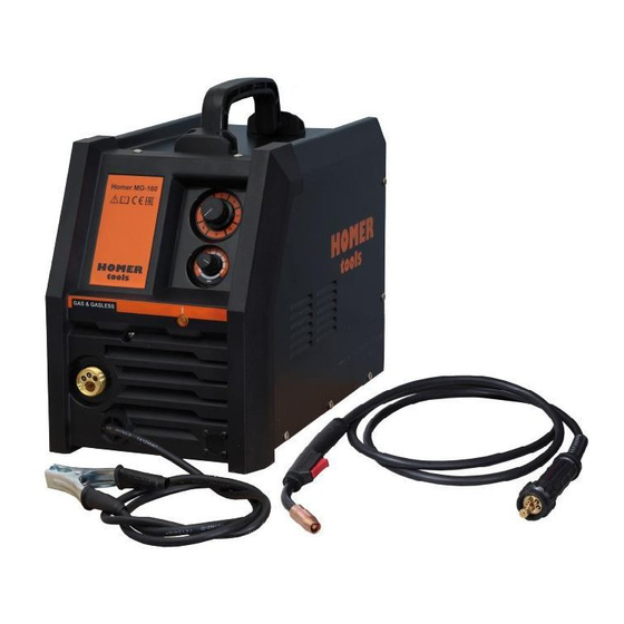
Page 10: Description Of The Appliance
-10- DESCRIPTION OF THE APPLIANCE MAIN PARTS Fig. 1 - Main parts ALFA IN a.s. © www.alfain.eu... - Page 11 Fig. 2 – Wire feeder Pos. Description QTB106 Feeder inlet liner QTB107 Fixing shaft QTB108 Pressure arm QTB109 Roll with plastic cup 6042 Roll 0,6-0,8 Homer MG-160 6043 Roll 0,6-0,8 Homer MG-160 TD QTB110 Torch inlet liner ALFA IN a.s. © www.alfain.eu...
-
Page 12: Getting Started
7. GETTING STARTED Getting started must be consistent with technical data and conditions of use. Homer MG-160 is equipped with a roller with two grooves - 0.6 and 0.8 mm. These grooves are intended for steel or aluminium solid wires of corresponding diameter. - Page 13 -13- 3. Put the inlet 11 onto the spool holder 10 followed by the spring and tighten up the nut onto the holder 10. 4. Cut off the curved or damaged end of welding wire and lead it through the feeder inlet liner 12, and the roll 15 into the torch inlet liner 16 (about 5 cm).
- Page 14 Solenoid valve Chain The gas cylinder cannot be fixed to the HOMER MG-160. It can be fixed onto the welders cart or other fixing appliance according to the user´s manual of such appliance and in accordance with the safety rules.
-
Page 15: Welding
-15- 8. WELDING SETTING WELDING CURRENT AND VOLTAGE When the wire had been installed and gas had been set it is possible to start welding. 1. The appliance must be plugged into the mains, the ON/OFF switch on "I". 2. To select the voltage use voltage switch 2. 3. -
Page 16: Routine Maintenance & Inspection
-16- TABLE OF WIRE CONSUMPTION DURING WELDING Wire Range of Maximal Wire consumption Wire Weight consumption wire feed wire feed per 1 minute of diameter of 1 m per 1 hour of speed speed welding [mm] wire [g] welding [m/min] [m/min] [g/min] [g/hour]... -
Page 17: Statement Of Warranty
The welder should also be wiped clean. If necessary, solvents that are recommended for cleaning electrical apparatus may be used. 3. Troubleshooting and repairing of HOMER tools welding equipment should only be carried out only by suitably qualified or competent person. -
Page 18: Disposal
-18- NOTE 7. Warranty repairs must be performed by either an ALFA IN Service Centre, an ALFA IN distributor or an Authorised Service Agent approved by the company ALFA IN. 8. As a warranty list serves proof of purchase (invoice) on which is the serial number of the machine, eventually a warranty list on the last page of this manual.
Need help?
Do you have a question about the MG-160 and is the answer not in the manual?
Questions and answers