Table of Contents
Advertisement
Quick Links
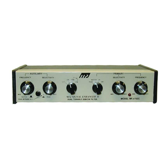
The improved MFJ-752C SIGNAL ENHANCER II is comprised of two tunable audio
filtering systems designed to clarity and remove interfering signals from both voice (SSB or AM)
and code (CW or RTTY) signals. This is accomplished by a primary filter which is a two-section,
four-pole variable filter which has PEAK, NOTCH, LOW PASS, and HIGH PASS functions, and
by an auxiliary filter which is a single section two pole PEAK or NOTCH filter. These two
independent filters allow you to remove interference while enhancing the desired signal.
1. Connect any 9-18V DC supply to the power jack on the back of the MFJ-752C. The adapter
must have a 2.1 mm coaxial plug with the center pin position and the sleeve ground. An
optional AC adapter, MFJ-1312B, 9-18VDC adapter is available from MFJ. A 12 VDC,
300mA supply is required to obtain the full two watts audio output.
2. Using the proper connector, connect a shielded cable from the external speaker or headphone
jack of the transceiver or receiver to the MFJ-752C. Use an RCA phono plug to connect to the
filter input. There are two inputs on the MFJ-752C allowing connection to two receivers for
greater convenience. The input is selected by the push button switch on the back of the MFJ-
752C.
3. Connect a speaker to the filter using shielded wire with a RCA phono plug at the filter speaker
output. For best results, use a 4 to 16 ohm speaker.
4. Headphone operation is accomplished by plugging headphones into the phone jack on the back
of the MFJ-752C. A mono plug or a stereo plug will work for headphone operation. With
stereo headphones, only one ear of the phones will work.
POWER SWITCH:
Selects power OFF, power ON, SSB Noise Limiter and CW Noise Limiter. The filter is bypassed
on the OFF position. NOTE: The noise limiter in not ON when the power switch is in the ON
position.
PRIMARY FILTER:
Function Selector: Selects PEAK, NOTCH, LOW PASS (LP), or HIGH PASS (HP) in the
primary filter.
Selectivity Control: Adjusts the bandwidth of the primary filter from 40 Hz to almost flat.
Frequency Control: Adjusts the center frequency of the peak, notch and the cutoff frequency of the
LOW PASS and HIGH PASS circuits approximately 300 Hz to 3000 Hz.
MFJ-752C SIGNAL ENHANCER II
INTRODUCTION
INSTALLATION
FRONT PANEL CONTROLS
1
Advertisement
Table of Contents

Summary of Contents for MFJ MFJ-752C SIGNAL ENHANCER II
- Page 1 INSTALLATION 1. Connect any 9-18V DC supply to the power jack on the back of the MFJ-752C. The adapter must have a 2.1 mm coaxial plug with the center pin position and the sleeve ground. An optional AC adapter, MFJ-1312B, 9-18VDC adapter is available from MFJ.
- Page 2 AUXILIARY FILTER: Function Switch: To select the PEAK function push button to the IN position. To select the NOTCH function push button to the OUT position. Frequency Control: Adjusts the center frequency of the auxiliary peak and notch circuits between approximately 300 Hz to 3000 Hz.
- Page 3 HIGH PASS: HIGH PASS mode is set by turning the Function Selector to HIGH PASS (HP). To remove unwanted low audio frequencies, set the SELECTIVITY and FREQUENCY controls for the desired response. AUXILIARY FILTER OPERATION PEAK: To set the auxiliary filter in the peak mode, simply push the FUNCTION button to the IN position. Set the SELECTIVITY control to about center range and adjust the FREQUENCY control to the desired signal.
- Page 4 ALIGNMENT The MFJ-752C primary filter is a two-stage filter which required proper aligned at the factory. If for any reason a realignment is necessary use the procedure below. UNDER NO OTHER CIRCUMSTANCES SHOULD THE INTERNAL TRIMMERS (R50 and R51) BE ADJUSTED.
- Page 5 ALIGNMENT PROCEDURE: 1. Connect scope input to the speaker output or phone output of the filter. 2. Connect signal generator to input 1 or 2 of the filter. Set the input switch on the filter accordingly. 3. Set signal generator for sine wave of 1V p-p and adjust generator frequency control(s) for a null (minimum amplitude).
Need help?
Do you have a question about the MFJ-752C SIGNAL ENHANCER II and is the answer not in the manual?
Questions and answers