Table of Contents
Advertisement
Quick Links
Instruction manual
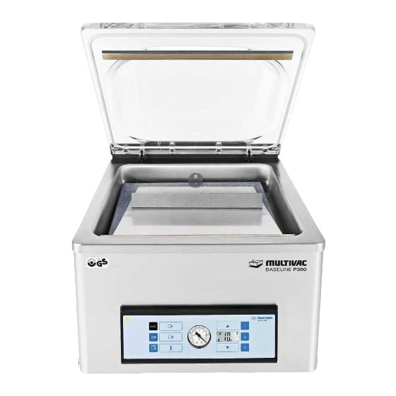
Chamber machine P300
MCB01
Serial number:
.........................................................
Service address:
Manufacturer:
MULTIVAC
Sepp Haggenmüller GmbH & Co. KG
Bahnhofstraße 4
D-87787 Wolfertschwenden, Germany
Tel.: 0049 8334 601 0
www.multivac.com
Date: 11.06.2014
The reproduction, distribution and utilization of this document as well as the communication of its contents to others without express authorization is
prohibited. Offenders will be held liable for the payment of damages. All rights reserved in the event of the grant of a patent, utility model or design.
Advertisement
Table of Contents

Subscribe to Our Youtube Channel
Related Manuals for multivac P300

Summary of Contents for multivac P300
- Page 1 Instruction manual Chamber machine P300 MCB01 Serial number: ............Service address: Manufacturer: MULTIVAC Sepp Haggenmüller GmbH & Co. KG Bahnhofstraße 4 D-87787 Wolfertschwenden, Germany Tel.: 0049 8334 601 0 www.multivac.com Date: 11.06.2014 The reproduction, distribution and utilization of this document as well as the communication of its contents to others without express authorization is...
-
Page 2: Table Of Contents
Contents Contents Important information on the manual ..................5 Machine documentation ...................... 5 Changes not covered in the manual..................5 Symbols used........................6 Safety..........................8 General safety instructions..................8 1.1.1 Target group....................8 1.1.2 Unauthorised modifications and manufacture of spare parts....... 10 EC Conformity...................... - Page 3 Contents Control terminal......................23 Display ........................24 Process sequence....................25 Times which have to be set..................26 Technical specifications ................... 27 Start-up..........................31 Setting up the machine and starting it up..............31 Operation ......................... 41 Opening and closing the chamber lid............... 41 Switching on the machine ..................
- Page 4 10.1 Disposing of the machine..................82 10.2 Dispose of operating materials................. 82 10.2.1 Disposing of oil and grease................82 10.2.2 Disposing of packaging materials ..............83 10.2.3 Dispose of chemicals ................... 83 Spare parts........................85 MULTIVAC branch offices......................87 11.06.2014...
-
Page 5: Important Information On The Manual
• Do not work with the machine until you have read through the manual and completely understood its contents. • Please contact MULTIVAC as soon as possible if there is some- thing you do not understand in the manual! Your comments will help us to further improve the manual. -
Page 6: Symbols Used
Important information on the manual Changes not covered in the manual you may discover slight deviations between the specifications in the manual and your machine. We also cannot rule out errors. The speci- fications, figures and descriptions in this manual do not constitute a legal contract between the manufacturer and customer. - Page 7 Important information on the manual Symbols used Press key C. • Enumerated items are marked with bullet points. – Dashes are used to mark sub-items of enumerated lists or se- quences of steps to be taken. 11.06.2014...
-
Page 8: Safety
Safety Safety General safety instructions The machine incorporates the latest technological principles. Never- theless, potential hazards for persons, the machine and other materi- als cannot be entirely excluded. • Before you start up the machine, read through the instruction manual and follow the instructions contained therein. •... - Page 9 Safety General safety instructions • The persons can ensure that the machine remains capable of op- eration. • The persons can perform maintenance work and inspections. The persons, who carry out work on electrical components, must have as a minimum requirement the following capabilities, knowledge and competence: •...
-
Page 10: Unauthorised Modifications And Manufacture Of Spare Parts
Genuine MULTIVAC spare parts and accessories provide the highest level of safety for personnel. Parts and equipment from other manu- facturers have not been tested by MULTIVAC and are therefore not approved. The use of such components can alter the properties of the machine and thereby impair safe operation. -
Page 11: Ec Conformity
Machinery Directive 2006/42/EC (exception: industrial trucks such as lift trucks and die changing trolleys). Agent authorised to compile the relevant technical documentation according to Directive 2006/42/EC: MULTIVAC Sepp Haggenmüller GmbH & Co. KG Department of Technical Services Bahnhofstraße 4 87787 Wolfertschwenden, Germany Manufacturer: MULTIVAC Sepp Haggenmüller GmbH &... -
Page 12: Electromagnetic Compatibility (Emc)
Safety Intended use Any other use is considered improper and can endanger persons, the product and the machine. 1.3.1 Electromagnetic compatibility (EMC) The machine has been designed for use in residential, business and industrial areas (without a separate power substation, it can be con- nected directly to the public mains). -
Page 13: Residual Risks
Safety Warning against incorrect use – Cleaning work. – Maintenance work. • Use of third-party parts, i.e. parts that are not MULTIVAC spare parts. • Operation under prohibited ambient conditions. Residual risks The safety instructions in this manual serve as guidelines for trained operating personnel in safe working practice with the machine. -
Page 14: Making The Selection Of Personnel
If necessary, order an instruction manual from the manufacturer in the appropriate official language. • Inform the personnel about measures for avoiding hygiene risks. • MULTIVAC offers appropriate training courses. 1.7.5 Providing personal protective equipment The operating company must ensure that the operators wear the re- quired personal protective equipment (foot protection, head gear, gloves, etc.) in accordance with the national directives which apply. -
Page 15: Provide Power Supply
Safety Obligations of the operating company 1.7.8 Provide power supply Connect the machine to the mains electricity at an always easily ac- cessible place. In the case of an emergency the machine must be capable of being disconnected immediately from the mains electricity. The power supply must be equipped as follows: •... -
Page 16: 1.7.10 Avoiding Hygiene Risks
Safety Obligations of the operating company • The operating company must ensure that the input and operating pressures given in the Technical specifications are adhered to and not exceeded. Personnel qualifications Only qualified persons with the corresponding required training, ex- perience and reliability may perform work on the gas supply. -
Page 17: 1.7.11 Checking The Packs
Safety Obligations of the operating company Health hazard! Insufficient or sporadic cleaning can promote the growth of micro- organisms which can change unfavourably the product that is to be WARNING packed. This can severely damage the health of people, especially of the consumers. -
Page 18: 1.7.12 Pump Protection Function
Safety Obligations of the operating company • Damage to the pack caused e.g. by sharp-edged products. Time of inspection • After machine start-up. • When a defined time interval was reached during running opera- tion. • When the pack size was changed. •... - Page 19 WARNING Unprotected danger zones can cause serious or even fatal injuries. Do NOT alter the safety devices. Use only MULTIVAC spare parts and accessories. Before switching on the machine each time: Check that all safety guards close completely and prevent reaching into the danger zones.
-
Page 20: Chamber Lid
Safety Danger zones 1.8.1 Chamber lid Danger of crushing! The gas strut is unhooked by opening the chamber lid completely. The chamber lid can therefore fall down unimpeded. CAUTION Reaching in between the housing and the falling chamber lid can lead to crushing injuries. - Page 21 Safety Machine labelling • If necessary, clean the labels with soap and water. – Do NOT clean the labels with solvents. • Replace damaged, scratched or illegible labels with new ones. Info Labels can be obtained from the manufacturer. Fig. 3: Safety labels and information labels Posi- Sign...
-
Page 22: Description
Description Description Construction of the machine Fig. 8: Construction of the machine Chamber lid Chamber lid gasket Counter-pressure bar Chamber Filling plates and sloping insert with support angle Sealing bar Inert gas nozzle (option) Power supply (Optional) Inert gas connection 10 Oil sight glass 11 Control terminal Optional equipment... -
Page 23: Control Terminal
Description Control terminal Control terminal Fig. 9: Control terminal <Machine control On/Off> key <Evacuation> key <Gas flushing> key Pressure display Display <Arrow> key Keys <1> to <3> <Arrow> key <Sealing> key 10 <Stop> key. 11 <Pump protection> key <Machine control •... -
Page 24: Display
Description Control terminal Display • Display process data. • Display settings. • Display diagnostic messages. <Arrow key> Increase values. Keys <1> to <3> Load and save recipes. <Arrow key> Decrease values. <Sealing> key Call up sealing time. <Stop> key. • Deactivate pump protection function With machines without inert gas: •... -
Page 25: Process Sequence
Description Display Numeric display • During the packaging procedure: display of the remaining time of the current process. • With chamber lid opened: display of the times currently set. Icon for pump protec- • Icon is not displayed: pump protection tion function is inactive. -
Page 26: Times Which Have To Be Set
Description Process sequence Evacuation Evacuation if chamber and film pouches. Gas flushing (option) Infeed of inert gas. Sealing Sealing of film pouches. Times which have to be set Times must be set for evacuation, gas flushing and sealing. The times depend on the product and the film pouch used. A pressure difference of at least -0.35 bar is required during the evacuation and gas flushing processes, so that the chamber lid remains closed. -
Page 27: Technical Specifications
Description Times which have to be set Time Explanation Gas flushing The film pouch is filled with inert gas during this time (option) time. The time depends on the input pressure at the inert gas connection and on the vacuum level reached in the chamber. - Page 28 Description Technical specifications Dimensions Weight approx. 68 kg Fig. 12: Dimensions Installation conditions and ambient conditions Ambient temperature +2 °C to +40 °C Storage temperature -25 °C to +80 °C Relative air humidity during op- 90 % non-condensing eration or storage of the ma- chine, max.
- Page 29 Description Technical specifications Inert gas (option) Max. input pressure 2.5 bar Min. input pressure 0.7 bar Inner diameter of supply line 8 mm Vacuum pump Vacuum pump 20 m Achievable final pressure approx. 2 mbar Noise exposure at the workplace Based on Machinery Directive (2006/42/EC)
- Page 30 Description Technical specifications Info The measured values of the noise data have been adjusted to take extraneous and ambient noises into account. Higher measured values may be produced as a result of the follow- ing: • Highly sound-reflecting rooms. • Modified settings. •...
-
Page 31: Start-Up
Start-up Start-up Setting up the machine and starting it up Danger of explosion! Operating the machine in a potentially explosive atmosphere can result in explosion due to hot machine parts. DANGER Explosions can cause serious injuries or even death. Do NOT use the machine in rooms that are exposed to explo- sion hazards. - Page 32 Start-up Setting up the machine and starting it up Position the machine on the site in such a way that the power supply is on the right side. Open the chamber lid. Open the chamber lid more than half way so that it remains open.
- Page 33 Start-up Setting up the machine and starting it up Close the chamber lid. So that the chamber lid remains closed, first open it as far as the limit stop and then close it. Unscrew the two screws at the rear of the machine. Turn these screws anticlockwise.
- Page 34 Start-up Setting up the machine and starting it up Lay a soft underlayer in front of the machine. – When the housing is opened, the control terminal lies on the underlayer. Ensure that the machine is not connected to the mains electricity. Open the housing completely (slightly more than 90 °).
- Page 35 Start-up Setting up the machine and starting it up Unscrew the screw plug. To do so, turn the screw plug anticlock- wise. Fill the vacuum pump with the oil supplied up to the middle of the oil sight glass. – The oil level is then approximately in the middle of the oil sight glass.
- Page 36 Start-up Setting up the machine and starting it up Check the oil level on the oil sight glass. If too much oil has been filled into the vacuum pump, drain off ex- cess oil: Position the machine such that a liquid container can be held under the oil sight glass.
- Page 37 Start-up Setting up the machine and starting it up Place filling plates under the base plate so that the base plate is even. Hold the liquid container (e.g. an oil bottle) under the drain opening. Unscrew the screw plug. To do so, turn the screw plug anti- clockwise.
- Page 38 Start-up Setting up the machine and starting it up Check the oil level on the oil sight glass. Turn the screw plug in the fill opening and screw it tight. To do so, turn the screw plug clockwise. Wipe off and remove any oil. Close the housing.
- Page 39 Start-up Setting up the machine and starting it up Tighten the two screws at the rear of the machine. Turn these screws clockwise. – The housing is closed and tight. Danger of explosion! Gas mixtures with oxygen proportions over 21% are explosive. A gas mixture with an oxygen proportion over 21 % can cause an DANGER explosion and fire if it comes in contact with heat, oil or grease.
- Page 40 Start-up Setting up the machine and starting it up Attach the gas hose to the inert gas connection of the machine. Fasten the hose with hose clamps. Open the stop-cock for the gas supply. Set the input pressure; see Technical Specifications. Check the mains voltage on the type plate and compare it with the voltage of the mains electricity.
-
Page 41: Operation
Operation Operation Opening and closing the chamber lid Open the chamber lid more than half way so that it remains open. – The chamber lid remains open in the middle position. So that the chamber lid remains closed, first open it as far as the limit stop and then close it. -
Page 42: Switching On The Machine
Operation Opening and closing the chamber lid To start the machine after it has been switched on, firmly press the opened chamber lid shut against the resistance by pressing the middle of its front edge. – The chamber is closed when the chamber lid is completely shut. -
Page 43: Setting The Times
Operation Switching off the machine Close the stop-cock for the gas supply, if part of the machine. If required disconnect the machine from the mains electricity. Setting the times Press the key for the desired function. – The icon of the function flashes in the display. To set the evacuation time, press the <Evacuation>... - Page 44 Operation Packing products If necessary, use filling plates. – The pouch neck should be located at the centre of the pouch height x. Use the sloping insert for packaging liquids, see Section 5.1 "I ". SERT AND REMOVE THE SLOPING INSERT –...
- Page 45 Operation Packing products Insert film pouch. – The opening of the film pouch should extend 2 to 3 cm beyond the sealing device. Gas flushing option: Pull the opening of the film pouch over the nozzles so that inert gas flows into the film pouch. Pull the pouch neck flat on the sealing bar.
-
Page 46: Aborting Evacuation
Operation Packing products Detach the pouch neck. Check the pack. Info Visually inspect the packs on a regular basis while the machine is running. Depending on product and pack it may be necessary to carry out additional and considerably more complex test proce- dures. -
Page 47: Working With Recipes
Operation Aborting packaging procedure To abort the packaging procedure, press the <Machine control On/Off> key. – The display goes dark. – The chamber is ventilated. – The chamber lid opens automatically. – The product is not packaged. Working with recipes 4.8.1 Load recipe Press the desired key briefly <1>... - Page 48 Operation Perform pump protection function To start the machine after it has been switched on, firmly press the opened chamber lid shut against the resistance by pressing the middle of its front edge. – The pump protection function starts. – The "pump protection" icon flashes. –...
-
Page 49: Adjustment Work And Setup
Adjustment work and setup Adjustment work and setup Insert and remove the sloping insert If necessary, use filling plates for the desired incline. Hook the sloping insert on the screws of the sealing bar. Attach the support angle to the sloping insert at the required posi- tion. -
Page 50: Cleaning
– Recommendations for the course of the daily cleaning. – Recommendations for the course of the intensive cleaning. – Qualifications of the cleaning personnel. Assign only suitably qualified and instructed personnel. Information on qualification and training can be obtained from MULTIVAC Service. • First aid measures. 11.06.2014... -
Page 51: Instructions For Maintaining The Machine's Value
Cleaning Notes on cleaning 6.1.2 Instructions for maintaining the machine's value Regular and proper care helps to maintain the machine's value. The best protection against harmful influences is to clean and disinfect the machine on a regular basis. The longer product residue and other aggressive deposits remain on the machine, the more harmful their corrosive effects will be. -
Page 52: Instructions On The Handling Of Cleansers
Cleaning Notes on cleaning • The temperature of the water must NOT exceed 60 °C (140 °F). • Only rinse off with water of drinking quality. 6.1.3 Instructions on the handling of cleansers Chemical burn hazard! Cleansers are caustic. Caustic effects are NOT noticed immedi- ately. -
Page 53: Instructions On The Handling Of Anti-Corrosion Agents And Lubricants
Cleaning Notes on cleaning 6.1.5 Instructions on the handling of anti-corrosion agents and lubricants Excess lubricants can accumulate at lubrication points. Excess grease has no lubricating function; however, it can breed micro- organisms and contaminate the product. • For type of anti-corrosion agent, refer to "Care products table". •... - Page 54 Cleaning Cleaning recommendations Allow the machine and sealing bar to cool down. Store empty, new film pouches outside the room in a clean, dry place during the cleaning procedure. Remove all waste (e.g. product scraps, film trim) on or around the machine.
- Page 55 Cleaning Cleaning recommendations If necessary, wipe off the components with a new cloth and water of drinking quality; see instructions of the disinfectant manufac- turer. Clean the floor with a rubber wiper. Dispose of the waste properly. Apply cleanser to the floor in the low-pressure foaming procedure. Wait until the contact time has elapsed (see instructions of cleanser manufacturer).
-
Page 56: Care Products Table
Cleaning Cleaning recommendations Attach the following components: – Sealing bar, see Section 7.3.2 "I ". NSTALL THE SEALING BAR – Filling plate. – Sloping insert with with support angle. Install the chamber lid gasket. If necessary, dry the chamber lid gasket and groove with a new cloth or sterile compressed air. - Page 57 Cleaning Care products table Type Manufacturer Designation Ecolab USA Quorum Pink II Diversey Europe Shureclean VK10 JD Shureclean Plus VK9 Diversey USA Shureclean VK10 JD Shureclean Plus VK9 Cleansers, alkaline Ecolab Europa P3-topactive LA Diversey Europe JD Ultraclean VK3 Diverfoam SMS HD VF22 Diversey USA JD Ultraclean VK3 Diverfoam SMS HD VF22...
- Page 58 Cleaning Care products table • Castrol: www.castrol.com • Klüber Lubrication: www.klueber.com 11.06.2014...
-
Page 59: Maintenance
Maintenance Maintenance Dangerous voltage! Switching off the machine does not rid it of electrical current. Touching electrically charged components can cause serious or DANGER even fatal injuries. Before performing any cleaning or service work: Disconnect the machine's power supply from the mains electric- ity. -
Page 60: Service Recommendation
Maintenance Maintenance schedule Every 1000 opearating hours or yearly Page Complet Vacuum pump Oil change Vacuum pump Exchanging the air de-oiling element Entire machine Check the age Service recommendation 7.2.1 Vacuum pump - Perform the pump protection func- tion Perform the pump protection function, see Section 4.9 "P ERFORM ". -
Page 61: Entire Machine - Alkaline Cleaning And Disinfection
Maintenance Service recommendation Check the chamber lid for damage (e.g scratches, cracks), defor- mation and misting. If the chamber lid is damaged, deformed or misted up, have it replaced by the service department. Check chamber lid gasket for damage. If necessary, replace the chamber lid gasket, see Section 7.8 "C ". -
Page 62: Vacuum Pump - Oil Change
7.2.10 Entire machine - Check the age Read the year of manufacture on the type plate. If the machine is older than 19 years: Shut down the machine. Have the safety functions checked by MULTIVAC Service. Replace the sealing bar 7.3.1 Remove the sealing bar Switch off the machine. -
Page 63: Install The Sealing Bar
Maintenance Replace the sealing bar Pull out the sealing bar. 7.3.2 Install the sealing bar Disconnect the machine from the mains electricity. Open the chamber lid. Open the chamber lid more than half way so that it remains open. – The chamber lid remains open in the middle position. Install the sealing bar on the carriers. - Page 64 Maintenance Repair counter-pressure bar Pull off the Teflon tape. Take the profile thread out of the counter-pressure bar. Cut the Teflon tape to the length of the profile thread. Press the new profile thread into the counter-pressure bar. Clean the profile thread. –...
-
Page 65: Open And Close The Housing
Maintenance Repair counter-pressure bar Smooth the Teflon tape flat. Open and close the housing 7.5.1 Open housing Open the chamber lid. Open the chamber lid more than half way so that it remains open. – The chamber lid remains open in the middle position. Take all the objects out of the chamber apart from the sealing bar. - Page 66 Maintenance Open and close the housing Lay a soft underlayer in front of the machine. – When the housing is opened, the control terminal lies on the underlayer. Ensure that the machine is not connected to the mains electricity. Burn hazard! The surface of the vacuum pump can reach temperatures of over 70 °C during operation.
-
Page 67: Close Housing
Maintenance Open and close the housing Open the housing completely (slightly more than 90 °). Close the chamber lid and hold it closed when opening the housing. – The whole control terminal is lying flat on the underlayer. – The base plate of the machine is raised at the pivot point of the housing by several centimetres. -
Page 68: Change The Oil In The Vacuum Pump
Maintenance Change the oil in the vacuum pump Change the oil in the vacuum pump 7.6.1 Drain oil Allow the machine and vacuum pump to cool down for 1 hour. Open housing, see Section 7.5.1 "O ". PEN HOUSING Unscrew the screw plug. To do so, turn the screw plug anticlock- wise. - Page 69 Maintenance Change the oil in the vacuum pump Position the machine such that a liquid container can be held un- der the oil sight glass. Place filling plates under the base plate so that the base plate is even. Hold the liquid container (e.g. an oil bottle) under the drain open- ing.
-
Page 70: Filling The Vacuum Pump With Oil
Maintenance Change the oil in the vacuum pump Unscrew the screw plug. To do so, turn the screw plug anticlock- wise. Drain the oil completely. Wipe off and remove any oil from the machine. Turn the screw plug in the drain opening and screw it tight. To do so, turn the screw plug clockwise. - Page 71 Maintenance Change the oil in the vacuum pump Unscrew the screw plug. To do so, turn the screw plug anticlock- wise. Fill the vacuum pump with oil up to approximately the middle of the oil sight glass. Use only oils that are approved by the manu- facturer, see 'Spare Parts' section or the spare parts catalogue.
-
Page 72: Change The Air De-Oiling Element
Maintenance Change the oil in the vacuum pump Check the oil level on the oil sight glass. – The oil level is then approximately in the middle of the oil sight glass. Turn the screw plug in the fill opening and screw it tight. To do so, turn the screw plug clockwise. - Page 73 Maintenance Change the air de-oiling element Allow the vacuum pump to cool down. Unscrew the screw plug. To do so, turn the screw plug anticlock- wise. Pull out the air de-oiling element and dispose of it properly. 11.06.2014...
-
Page 74: Change Chamber Lid Gasket
Maintenance Change the air de-oiling element Attach a sealing ring to the new air de-oiling element. Insert a new air de-oiling element with sealing ring. – The arrow on the air de-oiling element points downwards. Place the screw plug, together with the spring, onto the air de- oiling element pipe and tighten it. -
Page 75: Check The Chamber For Leaks
Maintenance Change chamber lid gasket Remove the chamber lid gasket from the groove. Press the new chamber lid gasket into the groove of the chamber lid. – The beginning and end of the chamber lid gasket must butt up against each other without a gap. During insertion, do not stretch the chamber lid gasket. - Page 76 Maintenance Check the chamber for leaks Set the evacuation time to 30 s with the <arrow keys>. To start the machine after it has been switched on, firmly press the opened chamber lid shut against the resistance by pressing the middle of its front edge. Pull the mains plug shortly before the evacuation time has elapsed.
-
Page 77: Troubleshooting
Troubleshooting Troubleshooting Injury hazard! Ignorance of proper machine handling is very dangerous. Improper handling can lead to serious injuries. WARNING For all service and repair work: Make sure you observe the safety instructions and accident prevention regulations. Disconnect the unit's power supply from the mains electricity. Only qualified electricians are permitted to work on electrical modules. - Page 78 Troubleshooting Faults without diagnostic message Symptom Cause Solution • Ambient temperature too low. • Operate the machine only at permissible ambient tempera- ture, see "Technical Specifica- tions". • Vacuum pump defective. • Notify the service. Chamber lid does not • Chamber lid pressed closed •...
- Page 79 Troubleshooting Faults without diagnostic message Symptom Cause Solution • Film pouch damaged. • Use a new film pouch. • Film pouch not suitable. • Use a film pouch suitable for sealing. • The pressure difference be- • Set the evacuation time and tween the chamber and the gas flushing time such that the outside environment is not...
-
Page 80: Shutdown, Transport, Storage
Shutdown, transport, storage Shutdown, transport, storage Info Observe the safety instructions, see Section 1 "S ". AFETY Shutting down the machine Close the chamber lid. Close the stop-cock for the gas supply, if part of the machine. If present, remove the gas hose from the inert gas connection. Disconnect the machine from the mains electricity. -
Page 81: Storing The Machine
Shutdown, transport, storage Storing the machine Storing the machine Shutting down the machine. Select a suitable storage site. Observe the ambient conditions for storing the machine, see Technical specifications. Ensure that the location site is of adequate load-bearing capac- ity and keep the weight of the unit in mind, see Technical speci- fications. -
Page 82: Disposal
Disposal Disposal 10.1 Disposing of the machine Info • Sealing bars can be reused on other machines of the same se- ries. • If disposal of the machine is not handled by the manufacturer, dispose of the machine as described below. Disconnect the machine from the mains electricity, see Section 9 "S ". -
Page 83: 10.2.2 Disposing Of Packaging Materials
Disposal Dispose of operating materials Info Excerpt from the disposal directive: • It is prohibited to mix used oil with other waste. • Used oils may NOT be mixed with each other. • Used oil filters should be collected, stored, transported and dis- posed of separately from other waste. - Page 84 Disposal Dispose of operating materials Handle cleansers and disinfectants properly and dispose of them in a professional manner. Info Improper disposal is harmful to the environment. • Observe the safety data sheets of the cleanser and disinfectant manufacturers. • Follow the disposal instructions of the cleanser and disinfectant manufacturers.
-
Page 85: Spare Parts
Spare parts Spare parts Illustration Material Designation Quantity and number unit of meas- urement 106624708 Sealing bar (completely pre- 1 pc. assembled) Fig. 14: Sealing bar Not illustrated. 105311871 Teflon tape for sealing bar (for 1.8 m four changes) 106739631 Wearing parts set for counter- 1 pc. - Page 86 Spare parts Fig. 16: Spare parts drawing for vacuum pump Maintenance set Item Material number Designation Quan- tity and unit of meas- ure- ment 105048117 Low odour synthetic oil for vac- uum pumps 91111114013 HD oil mineral oil Not suitable for the packaging of food.
-
Page 87: Multivac Branch Offices
MULTIVAC branch offices MULTIVAC branch offices GERMANY MULTIVAC Sepp Haggenmüller GmbH & Co. KG Tel.: +49 83 34 601 0 Fax:+49 83 34 601 199 multivac@multivac.de www.multivac.com SWITZERLAND MULTIVAC EXPORT AG Tel.: +41 41 785 65 65 Fax:+41 41 785 65 10 meag@multivac.ch... - Page 88 INDIA IRELAND ISRAEL MULTIVAC Laraon India Pri- MULTIVAC Ireland Ltd. MULTIVAC B.P.S. Ltd. vate Limited Tel.: +353 (0) 1 4133200 Tel.: +972 46 344 68 1 Tel.: +91 12 446 10 000 Fax:+353 (0) 1 4133205...
- Page 89 MULTIVAC branch offices AUSTRIA POLAND PORTUGAL MULTIVAC Vertriebsgesell- MULTIVAC Sp. z o. o. Multi Vacuo - Sistemas de Embal- schaft mbH Tel.: +48 81 746 67 00 agens Lda. Tel.: +43 (0)1 698 1300 Fax:+48 81 746 67 01 Tel.: +351 21 41 95 541 Fax:+43 (0)1 698 1300-99 mupl@multivac.pl...
- Page 90 MULTIVAC branch offices HUNGARY UNITED ARAB EMIRATES MULTIVAC Hungária Kft. MULTIVAC, Inc. MULTIVAC Middle East (FZE), Tel.: +36 23 500 28 7 Tel.: +800 877 5200 Amir Sotoudeh Fax:+36 23 500 28 8 Tel.: +1 816 891 0555 Tel.: +971 4 299 1980 info@hu.multivac.com...
Need help?
Do you have a question about the P300 and is the answer not in the manual?
Questions and answers