Table of Contents
Advertisement
Quick Links
DR7000 SERIES
DR7000 SERIES
DR7000 SERIES
DR7000 SERIES
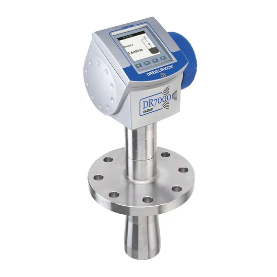
Radar Level Instrument for 2-wire control systems
(liquids)
Supplementary Instructions for ATEX applications
Supplementary Instructions for ATEX applications
Supplementary Instructions for ATEX applications
Supplementary Instructions for ATEX applications
© AMETEK Drexelbrook - EDO 11-10-112, DR7000-LM ATEX, Issue #2
Supplementary instructions
Supplementary instructions
Supplementary instructions
Supplementary instructions
Advertisement
Table of Contents

Summary of Contents for Ametek Drexelbrook DR7000 Series
- Page 1 Supplementary instructions Radar Level Instrument for 2-wire control systems (liquids) Supplementary Instructions for ATEX applications Supplementary Instructions for ATEX applications Supplementary Instructions for ATEX applications Supplementary Instructions for ATEX applications © AMETEK Drexelbrook - EDO 11-10-112, DR7000-LM ATEX, Issue #2...
-
Page 2: Table Of Contents
CONTENTS DR7000 SERIES 1 General safety information 1.1 Scope of the document..................... 4 1.2 Device description ......................4 1.3 Standards and approvals....................4 1.4 Device categories ......................5 1.4.1 Ex ia / Ex iaD-approved devices....................5 1.4.2 Ex d[ia] / Ex tD[iaD]-approved devices ................... 5 1.4.3 Ex nA devices .......................... - Page 3 CONTENTS DR7000 SERIES 5 Service 5.1 Periodic maintenance..................... 22 5.2 Keep the device clean..................... 22 5.3 Returning the device to the manufacturer..............22 5.3.1 General information......................22 5.3.2 Form (for copying) to accompany a returned device............23 www.drexelbrook.co EDO 11-10-112, DR7000-LM ATEX, Issue #2...
-
Page 4: General Safety Information
GENERAL SAFETY INFORMATION DR7000 SERIES 1.1 Scope of the document These instructions are applicable only to the explosion-protection version of the radar level transmitter. For all other data, use the Quick Start and Handbook. If you do not have these documents, please contact the nearest office or download them from the manufacturer's internet site. -
Page 5: Device Categories
GENERAL SAFETY INFORMATION DR7000 SERIES 1.4 Device categories 1.4.1 Ex ia / Ex iaD-approved devices These devices are suitable for use in potentially explosive atmospheres of all flammable substances in Gas Groups IIA, IIB and IIC. The Ex ia-approved device is certified for applications requiring Category 1 G (gases, vapours or mists), 1/2 G or 2 G equipment when fitted with the appropriate options. -
Page 6: Atex Nameplates
GENERAL SAFETY INFORMATION DR7000 SERIES 1.5 ATEX nameplates Figure 1-1: Ex ia / Ex iaD nameplate (4...20 mA output) Figure 1-2: Ex ia / Ex iaD nameplate (PROFIBUS PA or FOUNDATION™ Fieldbus output) 1 ATEX certification agency code 2 Equipment category (explosive atmosphere - gas) 3 Types of device protection including approved Gas Groups (IIA, IIB or IIC) and temperature classes (T6...T3) - Page 7 GENERAL SAFETY INFORMATION DR7000 SERIES Figure 1-3: Ex d[ia] / Ex tD[iaD] nameplate (4...20 mA output) Figure 1-4: Ex nA nameplate (4...20 mA output) 1 ATEX certification agency code 2 Equipment category (explosive atmosphere - gas) 3 Types of device protection including approved Gas Groups (IIA, IIB or IIC) and temperature classes (T6...T3) 4 Equipment category (explosive atmosphere - gas), types of device protection including approved Gas Groups (IIA, IIB or IIC) and temperature classes (T6...T3)
-
Page 8: Installation
INSTALLATION DR7000 SERIES 2.1 Precautions 2.1.1 General notes WARNING! When you install the device, obey the conditions in the EC-Type Examination certificate. These conditions include: The special conditions for safe use. • The Essential Health and Safety Requirements. • The certificate is given on the CD-ROM supplied with the device. You can also download the certificate from our internet site. -
Page 9: Special Conditions
INSTALLATION DR7000 SERIES Figure 2-2: Risk of ESD 1 Sun cover 2 Drop antenna 3 Flange plate protection (option for the Drop antenna) 2.1.3 Special conditions WARNING! Aluminium housing: Possible source of ignition in a potentially explosive atmosphere. The housing is made of either aluminium alloy or stainless steel. If the device has an aluminium alloy housing, make sure that iron/steel objects do not hit or rub against the device. -
Page 10: Operating Conditions
INSTALLATION DR7000 SERIES INFORMATION! If delivered with the device, the purging connection is plugged with a NPTF screw and engaged ¼ on a minimum of 3 threads. ½ Connection and operation of the purging connection are the responsibility of the user. The operator is also responsible for selection of a suitable fluid to purge the device. - Page 11 INSTALLATION DR7000 SERIES Equipment category 2 G, 2/3 G or 3 G: Ex ia and Ex d[ia] devices - with the 4...20 mA output option Temperature Ambient temperature Flange temperature class Hygienic antennas Drop and horn Drop and horn antennas...
- Page 12 INSTALLATION DR7000 SERIES Equipment category 2 G, 2/3 G or 3 G: Ex ia and Ex d[ia] devices - with the PROFIBUS PA or FOUNDATION™ Fieldbus output options Temperature Ambient temperature Flange temperature class Hygienic antennas Drop and horn Drop and horn...
-
Page 13: Maximum Surface Temperature Of The Housing
INSTALLATION DR7000 SERIES 2.2.2 Maximum surface temperature of the housing Equipment category 1 D: Ex iaD devices only Equipment category 1/2 D, 2 D, 2/3 D or 3 D: Ex iaD and Ex tD[iaD] devices only Max. ambient temperature Max. flange Max. -
Page 14: Electrical Connections
ELECTRICAL CONNECTIONS DR7000 SERIES 3.1 General notes WARNING! • De-energize the circuit. Use the applicable cable glands for the cable entry openings in the housing (M20×1.5 or • NPT). For the cable entry size, refer to the device nameplate. ½... -
Page 15: How To Close The Terminal Compartment
ELECTRICAL CONNECTIONS DR7000 SERIES 3.2.2 How to close the terminal compartment DANGER! Ex d applications Ex d applications Ex d applications Ex d applications Make sure that the terminal compartment is correctly sealed. An explosion can cause death or injury to personnel and/or damage to equipment. Obey the instructions that follow: Ex d / Ex tD applications •... -
Page 16: Maximum Intrinsically-Safe Values For The Electrical Circuit
ELECTRICAL CONNECTIONS DR7000 SERIES 3.5.2 Maximum intrinsically-safe values for the electrical circuit INFORMATION! The optional second output is galvanically isolated from the main power supply, output 1 and parts of the device that are grounded. Level transmitter with the 4...20 mA output option (output terminal 1 or 2) ≤30 V... -
Page 17: Electrical Schema
ELECTRICAL CONNECTIONS DR7000 SERIES 3.5.4 Electrical schema Figure 3-2: Electrical schema for Ex i-approved equipment with the 4...20 mA output option Figure 3-3: Electrical schema for Ex i-approved equipment with the FOUNDATION™ Fieldbus or PROFIBUS PA output option 1 Intrinsically-safe power supply (use a second power supply for optional terminal 2 if the device has two 4...20 mA out-... -
Page 18: Ex D[Ia] / Ex Td[Iad] Equipment
ELECTRICAL CONNECTIONS DR7000 SERIES 3.6 Ex d[ia] / Ex tD[iaD] equipment 3.6.1 General notes Ex d[ia]- and Ex tD[iaD]-approved equipment have two separate compartments. The electronics in the electronics block compartment are Ex ia / ExiaD-approved and the terminals compartment is Ex d / Ex tD-approved. -
Page 19: Supply Voltage
ELECTRICAL CONNECTIONS DR7000 SERIES CAUTION! Do not ground the positive connection. 3.6.3 Supply voltage Current output terminal Minimum voltage at output Maximum voltage at output terminal [VDC] terminal [VDC] 1 (U 2 (U 1 Minimum voltage at output terminal for a current output of 22 mA 2 Optional. -
Page 20: Ex Na Equipment
ELECTRICAL CONNECTIONS DR7000 SERIES 3.7 Ex nA equipment 3.7.1 How to connect the electrical cables INFORMATION! Cable entries are supplied on customer demand. If you supply the cable entries, this part • must have a degree of ingress protection IP≥54 (EN 60529). -
Page 21: Start-Up
START-UP DR7000 SERIES WARNING! Make sure that it is safe to supply electrical power. Do a start-up check: • Are the wetted components (gasket, flange and antenna) resistant to corrosion by the tank product? • Does the information given on the nameplate agree with the application? •... - Page 22 SERVICE DR7000 SERIES 5.1 Periodic maintenance No maintenance is necessary. 5.2 Keep the device clean DANGER! Risk of electrostatic discharge from the blue plastic sun cover, Drop antenna and the flange plate protection (an option for the Drop antenna). WARNING! Do not clean plastic parts in a hazardous area.
- Page 23 SERVICE DR7000 SERIES 5.3.2 Form (for copying) to accompany a returned device Company: Address: Department: Name: Tel. No.: Fax No.: The meter enclosed, type: Manufacturer's Order or Serial No.: has been operated with the following liquid: Because this liquid is:...
- Page 24 AMETEK Drexelbrook makes no warranty of any kind with regard to the material contained in this manual, including, but not limited to, implied warranties or fitness for a particular purpose. Drexelbrook shall not be liable for errors contained herein or for incidental or consequential damages in connection with the performance or use of material.
Need help?
Do you have a question about the DR7000 Series and is the answer not in the manual?
Questions and answers