Advertisement
Quick Links
This manual covers the following models:
• T855
Thermostat Applications Guide
D
e
c s
i r
t p
o i
n
Gas or Oil Heat
Electric Furnace
Heat Pump (No Aux. or Emergency Heat)
Heat Pump (with Aux. or Emergency Heat)
Multi-stage Systems
Heat Only Systems
Heat Only Systems
Cool Only Systems
Millivolt
Table of Contents
Una versión española de este
manual puede ser descargada
en www.pro1iaq.com
® U.S. Registered Trademark. Patents pending.
Copyright © 2006 Pro1 IAQ, Inc. All rights reserved.
INSTALLATION MANUAL
Power Type
Battery Power
Hardwire (Common Wire)
Yes
Yes
Hardwire (Common Wire) with Battery Backup
Yes
Yes
Yes
Yes
Yes
Yes
Yes
Page
A trained, experienced technician
must install this product.
2
3
Carefully read these instructions. You
4
could damage this product or cause a
5
hazardous condition if you fail to follow
6-8
these instructions.
9
10-12
13
Need Help?
For assistance with this product please visit
http://www.pro1iaq.com or call Pro1
Customer Care toll-free at 888-Pro1iaq
(776-1427) during normal business hours
(Mon-Fri 9 AM - 6 PM Eastern)
1
Rev. 0850
Advertisement

Subscribe to Our Youtube Channel
Related Manuals for Pro 1 IAQ True Comfort T855


Summary of Contents for Pro 1 IAQ True Comfort T855
-
Page 1: Table Of Contents
INSTALLATION MANUAL This manual covers the following models: • T855 Power Type Thermostat Applications Guide Battery Power Hardwire (Common Wire) Gas or Oil Heat Electric Furnace Hardwire (Common Wire) with Battery Backup Heat Pump (No Aux. or Emergency Heat) Heat Pump (with Aux. or Emergency Heat) Multi-stage Systems Heat Only Systems Heat Only Systems... -
Page 2: Installation Tips
INSTALLATION TIPS Wall locations The thermostat should be installed approximately 4 to 5 feet above the floor. Select an area with average temperature and good air circulation. Do not install thermostat in locations: • Close to hot or cold air ducts •... -
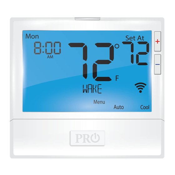
Page 3: Thermostat Quick Reference
Getting to know your thermostat Hold is displayed when thermostat program is Displays the user Indicates the permanently overridden. selectable setpoint current room temperature. Days of the temperature. +1 will appear in the week and time display when second stage of heat or cool is on. -
Page 4: Subbase Installation
SUBBASE INSTALLATION Caution: Mercury Notice: Electrical Hazard All of Pro1’s products are mercury free. However, if the Failure to disconnect the product you are replacing power before beginning to contains mercury, dispose of it install this product can cause properly. Your local waste electrical shock or equipment management authority can give damage. -
Page 5: Wiring
WIRING Wiring Warning: If you are replacing a thermostat, make All components of the control note of the terminal connections on the system and the thermostat thermostat that is being replaced. In some installation must conform to cases the wiring connections will not be color coded. -
Page 6: Technician Setup Menu
TECHNICIAN SETUP MENU Technician Setup Menu This thermostat has a technician setup menu Configure the installer options as desired using the table below. for easy installer configuration. To set up the thermostat for your particular application: Use the keys to change settings and the NEXT STEP Press MENU button or PREV STEP key to move from one... - Page 7 TECHNICIAN SETUP MENU Tech Setup Steps (Continued from the previous page) Heating Cooling ºF or ºC 12 or 24 Morning Program Temperature Temperature Hour Clock Operation Recovery Options Setpoint Limit Setpoint Limit This feature This feature You can select This feature turns your You can configure this Select F for Select GAS for...
- Page 8 TECHNICIAN SETUP MENU Tech Setup Steps (Continued from the previous page) Display Contractor Beep Heat Pump System Gas Auxiliary Stages Cooling Fan Light Call Number Switch for Heat Pump of Heat Delay The display light Allows you to put When any key When turned on You can configure the You can configure the...
-
Page 9: Mounting And Battery Installation
MOUNT THERMOSTAT & BATTERY INSTALLATION Mount Thermostat Align the 4 tabs on the subbase with corresponding slots on the back of the thermostat, then push gently until the thermostat snaps in place. On the back of the thermostat insert 2 AA Alkaline batteries (included). -
Page 10: Programming The Thermostat
PROGRAMMING THE THERMOSTAT Set Time Follow the steps below to set the day of the week and current time: Press MENU Press SET TIME Day of the week will be flashing. Use the key to select the current day of the week. Press NEXT STEP The current hour is flashing. - Page 11 PROGRAMMING THE THERMOSTAT You can use the table below to plan your customized program schedule if using 5+1+1. Programming Table Setpoint Setpoint Day of the Events Time Temperature (Cool) Temperature (Heat) Week Weekday Wake Leave Return Sleep Saturday Wake Leave Return Sleep Sunday...
- Page 12 PROGRAMMING THE THERMOSTAT To customize your 7 day program schedule, follow these steps: Monday Select HEAT or COOL using the system key. You have to program heat and cool each separately. Press MENU Press SET SCHED Note: Monday is displayed and the WAKE icon is shown. You are now programming the WAKE time period for the Monday setting.
-
Page 13: Specifications
SPECIFICATIONS & CONTACT INFORMATION Specifications The display range of temperature 41ºF to 95ºF (5ºC to 35ºC) The control range of temperature 44ºF to 90ºF (7ºC to 32ºC) Load rating 1 amp per terminal, 1.5 amp maximum all terminals combined Display accuracy ±...
Need help?
Do you have a question about the True Comfort T855 and is the answer not in the manual?
Questions and answers