U-Line Wine Captain 1000 Series User Manual & Service Manual
24" single zone
Hide thumbs
Also See for Wine Captain 1000 Series:
- User manual & service manual (59 pages) ,
- User manual (38 pages) ,
- Use and care manual (20 pages)
Table of Contents
Advertisement
Quick Links
USER GUIDE & SERVICE MANUAL
SAFETY • INSTALLATION & INTEGRATION • OPERATING INSTRUCTIONS • MAINTENANCE • SERVICE
RIGHT PRODUCT. RIGHT PLACE. RIGHT TEMPERATURE. SINCE 1962.
1000 Series
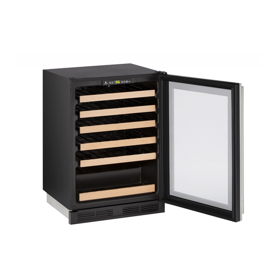
1224WC
24" Single Zone Wine Captain
®
•
•
Model
SAFETY • INSTALLATION & INTEGRATION • OPERATING INSTRUCTIONS • MAINTENANCE • SERVICE
Advertisement
Table of Contents
Troubleshooting

Related Manuals for U-Line Wine Captain 1000 Series


Summary of Contents for U-Line Wine Captain 1000 Series
- Page 1 USER GUIDE & SERVICE MANUAL SAFETY • INSTALLATION & INTEGRATION • OPERATING INSTRUCTIONS • MAINTENANCE • SERVICE RIGHT PRODUCT. RIGHT PLACE. RIGHT TEMPERATURE. SINCE 1962. 1000 Series 1224WC 24" Single Zone Wine Captain ® • • Model SAFETY • INSTALLATION & INTEGRATION • OPERATING INSTRUCTIONS • MAINTENANCE • SERVICE...
-
Page 2: Table Of Contents
Recommended Wine Storage WELCOME TO U-LINE Congratulations on your U-Line purchase. Your product comes from a company with over five decades of premium modular ice making, refrigeration, and wine preservation experience. U-Line continues to be the American leader, delivering versatility and flexibility for multiple applications including residential, light commercial, outdoor and marine... - Page 3 1. U-Line Customer Care must be contacted immediately at +1.800.779.2547. 2. Service or repairs performed on the unit without prior written approval from U-Line is not permitted. If the unit has been altered or repaired in the field without prior written approval from U-Line, claims will not be eligible.
-
Page 4: Safety And Warning
USER GUIDE SAFETY • INSTALLATION & INTEGRATION • OPERATING INSTRUCTIONS • MAINTENANCE • SERVICE Safety and Warning User Guide. Do not damage the refrigerant circuit. NOTICE WARNING Please read all instructions before installing, operating, or servicing the appliance. Service must be done by factory authorized service personnel. -
Page 5: Disposal And Recycling
USER GUIDE u-line.com Disposal and Recycling DANGER RISK OF CHILD ENTRAPMENT. Before you throw away your old refrigerator or freezer, take off the doors and leave shelves in place so children may not easily climb inside. If the unit is being removed from service for disposal,... -
Page 6: Environmental Requirements
USER GUIDE u-line.com SAFETY • INSTALLATION & INTEGRATION • OPERATING INSTRUCTIONS • MAINTENANCE • SERVICE Environmental Requirements This model is intended for indoor/interior applications only and is not to be used in installations that are open/ exposed to natural elements. - Page 7 USER GUIDE u-line.com SAFETY • INSTALLATION & INTEGRATION • OPERATING INSTRUCTIONS • MAINTENANCE • SERVICE Electrical WARNING SHOCK HAZARD — Electrical Grounding Required. Never attempt to repair or perform maintenance on the unit until the electricity has been disconnected. Never remove the round grounding prong from the plug and never use a two-prong grounding adapter.
-
Page 8: Cutout Dimensions
Electrical 1 Cutout Dimensions PREPARE SITE Your U-Line product has been designed for either freestanding or built-in installation. When built-in, your unit does not require additional air space for top, sides, or rear. However, the front grille must NOT be obstructed, and clearance is required for an electrical connection in the rear. -
Page 9: Product Dimensions
USER GUIDE u-line.com SAFETY • INSTALLATION & INTEGRATION • OPERATING INSTRUCTIONS • MAINTENANCE • SERVICE Product Dimensions... -
Page 10: Side By Side Installation
USER GUIDE u-line.com SAFETY • INSTALLATION & INTEGRATION • OPERATING INSTRUCTIONS • MAINTENANCE • SERVICE Product Dimensions 1 Side-by-Side Installation 4. Gently push units into position. Be careful not to entangle the electrical cord or water line, if Two units may be installed side-by-side. -
Page 11: Anti-Tip Bracket
USER GUIDE u-line.com SAFETY • INSTALLATION & INTEGRATION • OPERATING INSTRUCTIONS • MAINTENANCE • SERVICE Anti-Tip Bracket 3. Remove grille and place a mark on the floor at the front of the unit. Also place a mark on the floor in 1. -
Page 12: General Installation
USER GUIDE u-line.com SAFETY • INSTALLATION & INTEGRATION • OPERATING INSTRUCTIONS • MAINTENANCE • SERVICE Surrounding 20-1/4" (514 mm) 20-1/4" (514 mm) area (Top view) 6. Use a 1/8" drill to make two starter holes and fasten the anti-tip brackets to the floor using the screws provided. - Page 13 USER GUIDE u-line.com SAFETY • INSTALLATION & INTEGRATION • OPERATING INSTRUCTIONS • MAINTENANCE • SERVICE General Installation 1 Integrated Frame NOTICE Due to differences in surrounding cabinetry the panel may not perfectly align with door. The procedure below is designed to provide a...
-
Page 14: Integrated Panel Dimensions 1
USER GUIDE u-line.com SAFETY • INSTALLATION & INTEGRATION • OPERATING INSTRUCTIONS • MAINTENANCE • SERVICE 2. Starting at corner, pull /4" BACK SURFACE MUST HAVE AMPLE FLAT SURFACE gasket away from door/ TO MOUNT OVERLAY FRAME FLAT AND WITHOUT INTERFERENCE drawer. - Page 15 8. Locate 6 of the #6x 1-1/4" (32 mm) screws door/drawer using provided with your unit. clamps. A robust tape may also be used. U-Line 9. Using a Phillips screwdriver, place one screw into recommends the use of each of the 6 pilot holes and screw down. Do not...
-
Page 16: Grille / Plinth Installation
USER GUIDE u-line.com SAFETY • INSTALLATION & INTEGRATION • OPERATING INSTRUCTIONS • MAINTENANCE • SERVICE Integrated Panel Installation 2 Grille - Plinth Installation REMOVING AND INSTALLING GRILLE WARNING Disconnect electric power to the unit before removing the grille. When using the unit, the grille (plinth strip/base fascia) must be installed. -
Page 17: Door Swing
USER GUIDE u-line.com SAFETY • INSTALLATION & INTEGRATION • OPERATING INSTRUCTIONS • MAINTENANCE • SERVICE Door Swing Wall Wall 1 /4" Min. 2-1/8 " Min. (54 mm ) Door Swing Door Swing Units have a zero clearance for the door to open 90°, when installed adjacent to cabinets. -
Page 18: Door Stop
SAFETY • INSTALLATION & INTEGRATION • OPERATING INSTRUCTIONS • MAINTENANCE • SERVICE Door Swing 1 Door Stop Your U-Line unit was shipped to you with the optional 90° pin(s). (Models that are 15" wide include 1 pin. Models that are 24" wide include 2 pins.) The unit’s door will open freely without a fixed opening angle limitation. -
Page 19: Door Adjust
USER GUIDE u-line.com SAFETY • INSTALLATION & INTEGRATION • OPERATING INSTRUCTIONS • MAINTENANCE • SERVICE Door Adjustments DOOR ALIGNMENT AND ADJUSTMENT Align and adjust the door if it is not level or is not sealing properly. If the door is not sealed, the unit may not cool properly, or excessive frost may form in the interior. - Page 20 USER GUIDE u-line.com SAFETY • INSTALLATION & INTEGRATION • OPERATING INSTRUCTIONS • MAINTENANCE • SERVICE 3. Remove door by tilting forward and lifting door off 3. Rotate gasket 180°, aligning notch with magnet bottom hinge. Retain shoulder washers; they will be assembly and pressing firmly into the gasket reused.
- Page 21 USER GUIDE u-line.com SAFETY • INSTALLATION & INTEGRATION • OPERATING INSTRUCTIONS • MAINTENANCE • SERVICE 1. Remove wine rack (see WINE RACK INSTALLATION in Maintenance). 2. Starting from the side that has the spacers (previously unaltered units will be on the right hand side from the factory), remove 2 screws, slide and spacer.
-
Page 22: Wood Trim Finishing
Not following this warning may cause the inner liner of the unit to have a permanent odor, which the warranty will not cover. U-Line recommends Minwax ® Brand Water Based Stains and Minwax Polycrylic ®... -
Page 23: Free Standing Kit
USER GUIDE u-line.com SAFETY • INSTALLATION & INTEGRATION • OPERATING INSTRUCTIONS • MAINTENANCE • SERVICE Wood Trim Finishing 1 Free Standing Kit The free standing kit is an optional accessory. It is only used when unit is not installed in surrounding cabinetry. -
Page 24: First Use
SAFETY • INSTALLATION & INTEGRATION • OPERATING INSTRUCTIONS • MAINTENANCE • SERVICE Free Standing Kit 1 First Use All U-Line controls are preset at the factory. Initial startup requires no adjustments. NOTICE U-Line recommends allowing the unit to run overnight before loading with product. - Page 25 USER GUIDE u-line.com SAFETY • INSTALLATION & INTEGRATION • OPERATING INSTRUCTIONS • MAINTENANCE • SERVICE First Use 1...
-
Page 26: Control Operation
USER GUIDE u-line.com SAFETY • INSTALLATION & INTEGRATION • OPERATING INSTRUCTIONS • MAINTENANCE • SERVICE Control Operation CONTROL FUNCTION GUIDE FUNCTION COMMAND DISPLAY/OPTIONS ON/OFF Unit will immediately turn ON or OFF. Press and release Press and release to leave interior Toggle lights Glass door wine and beverage centers only. - Page 27 The unit will still maintain internal temperatures and set points. View a full list of Star-K certified U-Line units at www.star- k.org. To enable Sabbath Mode: 1. Press...
-
Page 28: Sabbath Mode 1
Anything in direct contact with the evaporator is subject to freezing. When properly loaded, your U-Line unit will store up to 48 (750 ml) bottles of wine. Airflow and Product Loading 1... -
Page 29: U-Line Wine Guide
Zinfandel, Cabernet French Rhone, Chateauneuf-du- Fish, Shell Fish, Crab, Dry White Wines, Light Italian Pape Barbaresco, Barolo Oysters Sparkling or Extra Dry Champagne Medium-Bodied Dry California Pinot Noir Bordeaux, French Burgundy Beef, Venison Full-Bodied Red Wines U-Line Wine Guide 1... - Page 30 Myth 4: Wine color does not change with aging. Common Tasting Terms IDEAL WINE STORAGE CONSIDERATIONS Terminology Description Acidity A critical element of wine that is responsible for preserving the wines freshness. Excess acidity results in an overly tart and sour wine. U-Line Wine Guide 2...
- Page 31 Wines can become flat or tired when voids and vacuums are created inside the wine bottle. In order to create voids and vacuums within a liquid, aggressive motion or shaking of the wine bottle would have to occur. U-Line Wine Guide 3...
- Page 32 Approximately 45°F (7°C) Sparkling Wine Captain Models - A Touch of Elegance ® In 1985 U-Line was the first North American appliance manufacturer to develop a residential wine storage unit, the Wine Captain ® . Each U-Line Wine Captain ®...
-
Page 33: Recommended Wine Storage
U-Line recommends arranging wine bottles as shown in the illustrations below. NOTE: After stocking, allow unit to stabilize product temperatures for 24 hours. -
Page 34: Cleaning
USER GUIDE u-line.com Recommended Wine Storage 1 SAFETY • INSTALLATION & INTEGRATION • OPERATING INSTRUCTIONS • • SERVICE MAINTENANCE Cleaning Polish and Cleaner or comparable product to prevent further problems. EXTERIOR CLEANING Vinyl Clad (Black or White) Using abrasive pads such as Scotchbrite™ will... - Page 35 USER GUIDE u-line.com Cleaning 1 SAFETY • INSTALLATION & INTEGRATION • OPERATING INSTRUCTIONS • • SERVICE MAINTENANCE High ambient temperature and excessive humidity can also produce frost. CAUTION DO NOT use an ice pick or other sharp instrument to help speed up defrosting. These instruments can puncture the inner lining or damage the cooling unit.
- Page 36 USER GUIDE u-line.com Cleaning 2...
-
Page 37: Cleaning Condenser
SAFETY • INSTALLATION & INTEGRATION • OPERATING INSTRUCTIONS • MAINTENANCE • SERVICE Cleaning Condenser INTERVAL - EVERY SIX MONTHS To maintain operational efficiency, keep the front grille free of dust and lint, and clean the condenser when necessary. Depending on environmental conditions, more or less frequent cleaning may be necessary. -
Page 38: Wine Rack Installation
USER GUIDE u-line.com SAFETY • INSTALLATION & INTEGRATION • OPERATING INSTRUCTIONS • MAINTENANCE • SERVICE USER GUIDE Wine Rack Installation To remove rack from the cabinet: 1. Remove any bottles stored on the rack. 2. Grasp the end of the rack and gently slide it out until it stops. -
Page 39: Extended Non-Use
If the unit will be exposed to temperatures of 40°F (5°C) or less, the steps above must be followed. For questions regarding winterization, please call U-Line at +1.800.779.2547. CAUTION Damage caused by freezing temperatures is not covered by the warranty. - Page 40 USER GUIDE u-line.com SAFETY • INSTALLATION & INTEGRATION • OPERATING INSTRUCTIONS • MAINTENANCE • SERVICE Extended Non-Use 1...
-
Page 41: Service
• Compressor: The compressor makes a hum or pulsing sound that may be heard when it operates. BEFORE CALLING FOR SERVICE If you think your U-Line product is malfunctioning, • Evaporator: Refrigerant flowing through an read the CONTROL OPERATION section to clearly evaporator may sound like boiling liquid. - Page 42 USER GUIDE u-line.com SAFETY • INSTALLATION & INTEGRATION • OPERATING INSTRUCTIONS • MAINTENANCE • SERVICE Causes which affect the internal temperatures of Problem Possible Cause and Remedy the cabinet include: Air temperature does not indicate product Product Is Not • Temperature setting.
- Page 43 One Year Limited Warranty For one year from the date of original purchase, this U-Line product warranty covers all parts and labor to repair or replace any part of the product that proves to be defective in materials or workmanship. For products installed and used for normal residential use, material cosmetic defects are included in this warranty, with coverage limited to 60 days from the date of original purchase.
-
Page 44: Warranty 1
• Food, beverage, and medicine loss are not covered by these warranties. • If the product is located in an area where U-Line factory authorized service is not available, you may be responsible for a trip charge or you may be required to bring the product to a U-Line factory authorized service location at your own cost and expense. - Page 45 USER GUIDE u-line.com SAFETY • INSTALLATION & INTEGRATION • OPERATING INSTRUCTIONS • MAINTENANCE • SERVICE Wire Diagram 1...
-
Page 46: Product Liability
The part that caused the damage must be returned to U-Line in its entirety. The part must be clearly labeled with the serial number of the unit it was removed from, the date, and the servicer who removed the part. -
Page 47: Warranty Claims
USER GUIDE u-line.com SAFETY • INSTALLATION & INTEGRATION • OPERATING INSTRUCTIONS • MAINTENANCE • SERVICE Product Liability 1 Warranty Claims • Alternatively, a Proof of Purchase (or equivalent) may submitted with the warranty claim to The following information defines the parameters for... - Page 48 USER GUIDE u-line.com SAFETY • INSTALLATION & INTEGRATION • OPERATING INSTRUCTIONS • MAINTENANCE • SERVICE Warranty Claims 1...
-
Page 50: Ordering Replacement
Some parts will require color or voltage information. If U-Line requires the return of original parts, we will inform you when the parts order is taken. This requirement will be noted on your packing list. A prepaid shipping label will be included with the replacement part. -
Page 51: System Diagnosis Guide
SAFETY • INSTALLATION & INTEGRATION • OPERATING INSTRUCTIONS • MAINTENANCE • SERVICE Ordering Replacement Parts 1 USER GUIDE System Diagnosis Guide REFRIGERATION SYSTEM DIAGNOSIS GUIDE System Suction Suction Compressor Condenser Capillary Evaporator Wattage Condition Pressure Line Discharge Tube Normal... - Page 52 USER GUIDE u-line.com SAFETY • INSTALLATION & INTEGRATION • OPERATING INSTRUCTIONS • MAINTENANCE • SERVICE To ensure the windings are not shorted, check the S Compressor Specifications 1 and R to ground. EMX20CLC Refrigerant R600a Voltage 115 - 127 VAC...
-
Page 53: Troubleshooting Extended
USER GUIDE u-line.com SAFETY • INSTALLATION & INTEGRATION • OPERATING INSTRUCTIONS • MAINTENANCE • SERVICE Troubleshooting - Extended NORMAL OPERATING SOUNDS All models incorporate rigid foam insulated cabinets to CAUTION provide high thermal efficiency and maximum sound Never attempt to repair or perform maintenance reduction for its internal working components. - Page 54 USER GUIDE u-line.com SAFETY • INSTALLATION & INTEGRATION • OPERATING INSTRUCTIONS • MAINTENANCE • SERVICE Test overload and relay, replace as needed. Compressor operating - no cooling Refer to System Diagnosis Guide. Evaporator fan not operating Use #19, Component Testing in Service Mode.
- Page 55 USER GUIDE u-line.com SAFETY • INSTALLATION & INTEGRATION • OPERATING INSTRUCTIONS • MAINTENANCE • SERVICE compressor will automatically deactivate during Check Voltage Alert Customer No Voltage an overload and will remain deactivated until the At Wall Outlet Of Power Failure overload switch cools.
- Page 56 USER GUIDE u-line.com SAFETY • INSTALLATION & INTEGRATION • OPERATING INSTRUCTIONS • MAINTENANCE • SERVICE Magnet Away From Switch Door Open Switch Open (Switch Closed) Troubleshooting - Extended 4...
- Page 57 USER GUIDE u-line.com SAFETY • INSTALLATION & INTEGRATION • OPERATING INSTRUCTIONS • MAINTENANCE • SERVICE Control Operation - Service UI BUTTON LAYOUT Hidden Button -Accesses Service Menu -No LED directly above. All LEDs turn on with button activation except #7.
- Page 58 USER GUIDE u-line.com SAFETY • INSTALLATION & INTEGRATION • OPERATING INSTRUCTIONS • MAINTENANCE • SERVICE CONTROL FUNCTION QUICK GUIDE FUNCTION COMMAND DISPLAY/OPTIONS ON/OFF Unit will immediately turn ON or OFF Press and release Glass door wine captains and beverage Press...
- Page 59 USER GUIDE u-line.com SAFETY • INSTALLATION & INTEGRATION • OPERATING INSTRUCTIONS • MAINTENANCE • SERVICE 4. Does not apply to this model. Adjust thermistor #2 offset 5. THERMISTOR 1 — ZONE OFFSET Adjust thermistor #3 offset (DO NOT MAKE AN ADJUSTMENT TO THIS WITHOUT...
- Page 60 USER GUIDE u-line.com SAFETY • INSTALLATION & INTEGRATION • OPERATING INSTRUCTIONS • MAINTENANCE • SERVICE Displays the number of defrosts that have Thermistor 1 open. occurred in the past 24 hours. Thermistor 2 open. Thermistor 3 open. Thermistor 4 open (Does not apply to this 23.
- Page 61 1. Disconnect the unit from power source. the appropriate model number*. 2. Push and hold the U-Line button. *(See Above “Model List”) 3. While still holding the U-Line button, plug the 5. Press light bulb button unit into the appropriate power source.
- Page 62 USER GUIDE u-line.com SAFETY • INSTALLATION & INTEGRATION • OPERATING INSTRUCTIONS • MAINTENANCE • SERVICE...
- Page 63 USER GUIDE u-line.com SAFETY • INSTALLATION & INTEGRATION • OPERATING INSTRUCTIONS • MAINTENANCE • SERVICE...
- Page 64 USER GUIDE u-line.com SAFETY • INSTALLATION & INTEGRATION • OPERATING INSTRUCTIONS • MAINTENANCE • SERVICE...
- Page 65 SAFETY • INSTALLATION & INTEGRATION • OPERATING INSTRUCTIONS • MAINTENANCE • SERVICE USER GUIDE Zone Thermistor If the zone thermistor in the unit fails, the unit will continue to cool in a backup mode (Self Preservation Mode) to preserve the integrity of the contents. The unit will otherwise operate normally.
-
Page 66: Defrost
SAFETY • INSTALLATION & INTEGRATION • OPERATING INSTRUCTIONS • MAINTENANCE • SERVICE Thermistor 1 1495 1247 1044 * (+/-5%) USER GUIDE Defrost The models below have automatic or frost free design and do not require manual defrosting under normal conditions. - Page 67 SAFETY • INSTALLATION & INTEGRATION • OPERATING INSTRUCTIONS • MAINTENANCE • SERVICE Pantry 42 (6) White Wine 45 (7) Red Wine 45 (7) Sparkling Wine 45 (7) Polar 42 (6) Deli 42 (6) Defrost 1...
Need help?
Do you have a question about the Wine Captain 1000 Series and is the answer not in the manual?
Questions and answers