Table of Contents
Advertisement
Quick Links
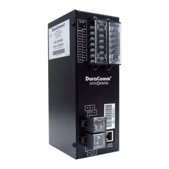
DC‐Powered Remote Monitoring and Control Unit
(These instructions are intended for use by a technician familiar with electronic products)
Remote Monitoring and Control Unit
Web Ready / Web GUI / Mobile Status Page
6 Isolated Voltage inputs with adjustable high and low
alarm thresholds. (CH 1 set to measure current)
4 Digital Outputs(Open‐Drain MOSFET)
4 Digital Inputs
Configure emails for alarms with external email account
SNMP Traps for Boot‐up and Alarms
SNMP Control of Digital Outputs
Remote reboot
2 User Levels with different permissions
Manual or NTP Time Setting
Temp Sensor Input (Uses LM35)
AC Voltage Monitor Input, 300 VAC
Monitoring Samples can be Logged and Downloaded
Battery backed up Real Time Clock to Timestamp Logged
New Live Information
Wide Input DC Supply Range, 9 to 60 VDC
Accessory Kit Supplied
3 year warranty
DESCRIPTION
The new DC-RMCU1 DC-Powered Remote Monitoring and Control Unit, provides the ability to remotely monitor AC Line
voltage up to 300 VAC, up to 6 DC Voltages and 1 temperature, monitor the status of up to 4 external alarms, as well as the ability to
remotely control the state of 4 digital open-drain MOSFET outputs, all via the internet using any standard web browser. The Channel 1
DC voltage input is configured at the factory to measure current using the included 100 Amp/50mV shunt. Additional channels can be
configured at the factory for current measurement. A mobile friendly version of the status page is also included. Alarms and email
notifications can be configured for the 6 analog voltage channels (high and low voltage), and email notifications can be configured for
the Alarm inputs. A high-temperature alarm threshold can be configured to send an email notification, as well as control one of the
digital outputs internally. The DC-RMCU1 also sends SNMP Traps for alarm conditions. The DC-RMCU can also be set to log
measurements to a 2 GB internal micro SD card, and the measurements are time-stamped with a real-time clock.
Guest users will see the status page that displays the AC Voltage, measured values and alarm condition of all active voltage
channels, temperature value and alarm condition, as well as alarm input status, and control status.
Admin and Control Users will be able to configure all of the input and output settings, and set the state of the digital outputs.
Admin and Control users can set device settings for logging, time, and Site Name.
Admin users have exclusive control of network configuration, including manual time setting or NTP, soft reboot of the DC-
RMCU1, factory reset of the entire configuration, and Control or Admin user passwords.
The DC-RMCU1 comes with the DuraComm three-year warranty.
DC‐RMCU1
Owners Guide
Advertisement
Table of Contents

Related Manuals for DuraComm DC-RMCU1

Summary of Contents for DuraComm DC-RMCU1
- Page 1 Alarm inputs. A high-temperature alarm threshold can be configured to send an email notification, as well as control one of the digital outputs internally. The DC-RMCU1 also sends SNMP Traps for alarm conditions. The DC-RMCU can also be set to log measurements to a 2 GB internal micro SD card, and the measurements are time-stamped with a real-time clock.
- Page 2 2 of 32 January 20, 2016...
-
Page 3: Table Of Contents
TABLE OF CONTENTS DESCRIPTION ............................................ 0 SPECIFICATIONS .......................................... 4 Accessory Kit (Included) ........................................ 4 INSTALLATION .......................................... 5 Input Power .......................................... 5 10/100 Ethernet ........................................... 5 DCRMU Board Layout and Configuration .................................. 6 Connecting TO The DC‐RMCU1 VIA the Internet ................................ 8 Prerequisites .......................................... 8 Determining the IP Address of the DC‐RMCU1 ................................. 8 Using DHCP .......................................... 8 Using Static DC‐RMCU1 IP and Network Configuration ............................... 8 Open a Web Connection to the DC‐RMCU1 ................................ 9 REMOTE Monitoring and Control Setup .................................. 10 User Login .......................................... 10 Network Setup .......................................... 11 Network Setup Notes ......................................... 11 SNMP Traps Setup .......................................... 12 Email Setup ............................................. 13 Email Setup Notes ........................................ 13 Device Setup ... -
Page 4: Specifications
SPECIFICATIONS Hardware Revision ................................... 2.0 Firmware Revision.................................... 2.4 DC Input Power ............................9 to 60 VDC @ 500 mA max Internal +5VDC supply current (Source for external Logic) ....................300 mA Max Voltage Input Channels (6 channels) – Max Voltage ......(Internally Isolated) +/-2 V with jumper, +/-100 V without jumper Digital Alarm Input Channel Thresholds (4 channels) ...... -
Page 5: Installation
INSTALLATION Input Power The DC‐RMCU1 DC PWR connections on the power strip. Please be sure to connect the positive terminal to the positive(+) supply lead, and the negative terminal to the negative(‐) supply lead. The supply voltage may be 9 VDC to 60 VDC. NOTE: The DC‐RMCU1 is “ON” as soon as power is applied. 10/100 Ethernet Connect the RJ‐45 on the DC‐RMCU1 to your network with an Ethernet patch cable. A short 3 foot cable is provided with the DC‐RMCU1. NOTE: The USB connector is for factory diagnostics only. 5 of 32 January 20, 2016... -
Page 6: Dcrmu Board Layout And Configuration
DCRMU Board Layout and Configuration Figure 1: PCB Layout The DC‐RMCU1 comes with a jumper installed on P1 to configure analog channel 1 for +/‐ 2 V to measure current shunt voltage. See the Sensor Setup Section for sensor wiring and configuration. Figures 2 and 3 Show connector wiring for the DC‐RMCU1 inputs for troubleshooting purposes. 6 of 32 January 20, 2016... - Page 7 Figure 2: J1 and J3 Wiring Figure 3: J2 Wiring 7 of 32 January 20, 2016...
-
Page 8: Connecting To The Dc-Rmcu1 Via The Internet
CONNECTING TO THE DC-RMCU1 VIA THE INTERNET Prerequisites System administrators must decide whether the DC‐RMCU1 will operate on the network with DHCP or a fixed IP address. The factory‐set DC‐RMCU1 will have these static addresses: IP address: 192.168.100.220, gateway address: 192.168.100.1, netmask: 255.255.255.0, and DNS address: 192.168.100.1. If you configure it to use DHCP, the DC‐RMCU1 will request an available IP address on your network. You will need to determine what address it has been given. If DHCP is not used, system administrators must also choose an unused IP address, and other network settings to use in the Network Setup screen. System administrators will also need to choose an email service and address to use for notifications, if needed. These will be used in the Email Setup Screen. DETERMINING THE IP ADDRESS OF THE DC-RMCU1 Power up the DC‐RMCU1 then connect the DC‐RMCU1 to the network with an Ethernet cable. A 3 foot cable is provided. Using DHCP The DC‐RMCU1 will attempt to connect to the network via DHCP when it is first connected, or when you perform a factory reset. You will need to get the IP address in one of two ways. You can get the IP address from the DHCP server’s client list, or you can use a PC on the same network to scan for the new IP address by using a software tool such as Angry IP Scanner. In Angry IP Scanner, you should add the MAC address “Fetcher” under “Tools > Fetchers”. The DuraComm MAC 70‐B3‐D5‐6B‐3. addresses all start with a base address of Write down the IP address of the DC‐RMCU1, then proceed to the section in this manual named “Open a Web Connection to the DC‐RMCU1”. Using Static DC-RMCU1 IP and Network Configuration If your network is not set up for DHCP, you will need to manually configure the settings to match the network it will be ... -
Page 9: Open A Web Connection To The Dc-Rmcu1
Open a Web Connection to the DC-RMCU1 Use your favorite device and browser (Chrome, Firefox, internet Explorer, etc.), and enter the IP address of the power supply on your network into the URL box on the browser (see the screenshot below). The DC‐RMCU1 should respond with the “Status” screen. 9 of 32 January 20, 2016... -
Page 10: Remote Monitoring And Control Setup
REMOTE MONITORING AND CONTROL SETUP Click “Network Setup” in the menu at the top of the screen. All setup requires an administrative user to log into the DC-RMCU1. See default passwords below. User Login Enter the user name and password. Factory default username and password are as follows: Admin Users have full control of the device. -
Page 11: Network Setup
NETWORK SETUP Network Setup Notes A network administrator for your company must choose the settings for this page. The default HTTP port is 80. If a different HTTP port is used, it will need to be added to the URL to access the RMCU. For example: if the port is changed to 8080 then the address would be changed to http://192.168.0.253:8080 NOTE: You must reboot the device for changes in these settings to take effect. 11 of 32 January 20, 2016... -
Page 12: Snmp Traps Setup
SNMP TRAPS SETUP This section is simplified, and meant for network administrators who already understand SNMP traps and how to configure capable equipment into their system. For those who want to understand the benefits of using SNMP traps, you can search for training material online under “SNMP Traps”, “MIB Browsers”, and “SNMP Monitoring”. The MIB file for the DC‐RMCU1 can be downloaded from the DC‐RMCU1 after you connect to it with your browser. Go to the Device Setup page and log in to the DC‐RMCU1. Halfway down the page there is a link to the MIB file. Right click on the link and click “Save Link As” to download the file. After download, import the MIB file into your MIB browser or Monitoring software to configure it for use with the DC‐ RMCU1. When the MIB file has been loaded, complete the “SNMP Setup” section on the “Network Setup” page of the DC‐RMCU1 to configure it for use with your monitoring solution. The DC‐RMCU1 will send traps for all configured alarm conditions including bootup, temperature, analog alarms, and digital alarms. 12 of 32 January 20, 2016... -
Page 13: Email Setup
EMAIL SETUP Email Setup Notes Enter the required email setup parameters given to you by your System Administrator. You can also send a test email from this screen. The example shows how to set up a Gmail account connection. Note: the Gmail account needs to be set 2‐step authorization “Off”. Log in to the Gmail account, go to account settings, go to the “Signing In” section, and verify that 2‐step authorization is “Off”. 13 of 32 January 20, 2016... -
Page 14: Device Setup
DEVICE SETUP 14 of 32 January 20, 2016... -
Page 15: Device Info
Device Info A custom site name can be entered here, and the model number, serial number, software version, and hardware version are shown here. Logging TheDC‐RMCU1will log all measurements and alarms to an SD card that is plugged into theDC‐RMCU1board. Users can set the rate here, as well as clear the card, or append new measurements. The CSV log file can be downloaded here, as well as the Status page. You can also examine the log file using a terminal connection through the USB port. If the SD card fills up, the oldest sample is discarded when a new one is stored. TheDC‐RMCU1custom device name is stored with the logged data, so that the source of the card can be identified after it removed from the RMCU. A DC‐RMCU1 connected to a battery backup power system can monitor and log information about AC mains power outages, as well as all the other measurements for as long as the battery backup lasts. When a log file reaches 5 MB, it is renamed, and a new one is started. Download all log files before clearing the log. With REV 2.4 Firmware, the DC‐RMCU1 has the ability to save log entries when an alarm occurs by choosing “Log Alarms” > “Yes”. You can log alarms, log periodically by setting the “Logging Rate” minutes, log both, or log none by choosing “Log Alarms”>”No” and setting the “Logging Rate” to “0”. The Alarm log entry is identified with label entry before the data entry, as in this example: Date and Time Settings Configuration for all date and time settings. Date and time is battery backed up on the card, and the values are saved in the logged samples. The real‐time‐clock can synchronize it’s time to the network through an NTP server, or it can be set manually if a network is not available. time.nist.gov or pool.ntp.org, The NIST NTP servers can be used by entering or another NTP server address into NTP Server box. Miscellaneous Settings The number of significant digits to the right of the decimal point for the analog channels can be configured here. Note: Best resolution is about 1 in 1000. Temperature can be configured to read in Fahrenheit or Celsius. 15 of 32 January 20, 2016... -
Page 16: Sensor Setup
SENSOR SETUP 16 of 32 January 20, 2016... -
Page 17: Sensor Setup Notes
Sensor Setup Notes The admin user can set custom names for each input or output. Factory set names will be supplied, but they can be re‐ written to be more descriptive, or to manage larger systems. Alarm colors can be set here to represent the proper logical state for your system. If any of the name fields on the left are left blank, the channel will be hidden on the status screen. Digital Outputs can be user‐configured to match your circuit. “Active” refers to the output MOSFET being “ON” or conducting. You may also configure each output to provide a positive or negative 500uS pulse. Button colors and orientation are also selectable. A user‐name for Active and Inactive states can also be configured. Analog and digital alarms are set up in the “Alarm Setup” screen. See the “Alarm Setup” section for more information. 17 of 32 January 20, 2016... -
Page 18: Sensor Calibration
SENSOR CALIBRATION 18 of 32 January 20, 2016... -
Page 19: Sensor Calibration Notes
Sensor Calibration Notes Sensor calibrations is provided to convert the native voltage measurements of the DC‐RMCU1 into other units for linear transducers. For example, the current transducer provided with the DC‐RMCU1 will have 50mv across it when 100 Amps is flowing through it. The conversion factor is entered on this page. Channels that only measure voltage do not need a conversion factor, and the entries can be left at 0. When a physical jumper is placed on channel 1, it is changed from a +/‐100 Volt max range to a +/‐2V max range to gain resolution for smaller voltages. The “Jumpered” drop‐down must be set to “Yes” for a channel with a jumper so that it is scaled properly. Since a current shunt is designed for a typical voltage drop of 50mv at full scale, Channel 1 is configured with a physical jumper, the “Jumpered” dropdown is set to “Yes”, and calibration factors are entered. Since 0 v will be equal to 0 Amps, we don’t need to change the lower left calibration factors. We change the vertical maximum to 0.05 VDC (50mv) and the horizontal maximum to 100. We then type “Amps” as the user units. By defining 2 points on the linear graph, we can calibrate any linear transducer, within the voltage measurement range of the DC‐RMCU1. This will allow you to use a broad range of existing transducers to measure many different things like pressure, temperature, force, etc. Even 4‐20ma transducers can be used by measuring the voltage across a resistor placed in series with the transducer. These transducers require that both the lower‐left and upper right calibration points be configured on the graph. 19 of 32 January 20, 2016... -
Page 20: Analog And Digital Wiring
ANALOG AND DIGITAL WIRING AC Line Voltage Measurement +12V DC‐RMCU1 Users AC Voltage 300 VAC Max Figure 4 Analog Channels: DC Voltage Measurement Figure 5 20 of 32 January 20, 2016... -
Page 21: Analog Channels: Dc Amperage Measurement
Analog Channels: DC Amperage Measurement The DC‐RMCU1 comes pre‐configured from the factory to measure amperage on channel 1. A jumper is installed on the board in the channel 1 circuit to configure it to measure +/‐2 V max instead of +/‐ 100 V max to measure the low voltage associated with the meter shunt. DC‐RMCU1 Channel 1 is calibrated to use the 100 Amp / 50mV shunt supplied with the DC‐RMCU1. To measure lower amperage ranges, please contact DuraComm technical support. Figure 6 Temperature Measurement Connect the LM35 Temperature sensor to the DC‐RMCU1 Temperature connector as shown. Figure 7 21 of 32 January 20, 2016... -
Page 22: Sensor Setup - Digital Inputs (Alarms)
Sensor Setup – Digital Inputs (Alarms) Figure 8 22 of 32 January 20, 2016... -
Page 23: Sensor Setup - Digital Open-Drain Outputs
Sensor Setup – Digital Open-Drain Outputs Digital output names have a unique configuration feature. To reverse the displayed logic of the digital output, just add a “+” character to the end of the name for that channel. Here are a couple of examples. Figure 9: Normal Digital Output Configuration Figure 10: Reversed Logic Digital Output Configuration 23 of 32 January 20, 2016... -
Page 24: Alarm Setup
ALARM SETUP 24 of 32 January 20, 2016... -
Page 25: Factory Default Alarm Settings
Alarm Setup To set up analog alarms, first you must select the alarm channel to set. This is accomplished by selecting the custom name of the channel in the dropdown box next to the “Analogs” label. For example, we are looking at the settings for the “Ammeter #1” channel in the screen above. “Ammeter #1” is the name given to this channel in the Sensor Setup screen. Note: The maximum temperature of the temperature sensor is +300 F. The low range of the sensor is about +36 F. The operating temperature range of the DC‐RMCU1 is ‐22 F to + 140 F This screen is where thresholds are set to define alarm conditions for the analog channels. You can choose to set an email notification when the alarm conditions are met, and you can assign the alarm to one of four alarm contacts. Factory Default Alarm Settings MEASUREMENT UNITS OVER ALARM OVER ALARM RECOVER UNDER ALARM UNDER ALARM RECOVER AC Line Voltage Volts 140 135 100 107 Temperature Fahrenheit 120 110 40 45 ... -
Page 26: User Setup
USER SETUP 26 of 32 January 20, 2016... -
Page 27: User Setup Notes
User Setup Notes Password changes and DC‐RMCU1 hard resets are perform by using this page. Care should be taken when changing any of these settings. Admin users of the DC‐RMCU1 with Revision 2.2 Firmware have access to a new calibration page. This page allows the user to calibrate a relationship between voltage measured and user units, such as Amperage. See the calibration page for more detail. The Admin user can also allow the Control user to perform this function by selecting Control User in the Calibration Access Dropdown list, and clicking Submit Values. NOTE: To hard reset your device back to factory settings, press the red button on theDC‐RMCU1PCB and hold it for more than 20 seconds. You will need to re‐connect to theDC‐RMCU1through your web browser by entering the factory supplied IP address and HTTP port (see Network Setup). Using the factory reset here or using the red button to reset will change the network settings back to the factory reset/default values shown in this manual on the network configuration page, even if your unit was custom set at the factory to a user IP address. If your unit was set to a custom IP address, it will be labeled underneath the product label on the side of the DC‐RMCU1. 27 of 32 January 20, 2016... -
Page 28: Status Screen
REMOTE MONITORING AND CONTROL STATUS PAGE Status screen This screen shows the status of all analog and digital inputs, as well as digital outputs. A user can also download the Log file from this page. AC Voltage is approximate. This example shows the factory settings. The temperature will show abnormally high readings if no LM35 temperature sensor is connected, because the input will float high. 28 of 32 January 20, 2016... -
Page 29: Mobile Status Screen
MOBILE STATUS SCREEN The following examples show a configured DC‐RMCU1 that is reading various voltages and currents. Any unused channels (configured with a blank name) are hidden in the desktop browser view, and grayed out in the mobile browser view. RMCU MAINTENANCE Battery The battery on theDC‐RMCU1is used to back up the real time clock for logging purposes. Logged in users can see the current system time on the Device Setup page under Date and Time settings. 29 of 32 January 20, 2016... -
Page 30: Conductor Pretreatment
CONDUCTOR PRETREATMENT All kinds of copper conductors can be clamped without treatment. DO NOT solder tin stranded conductors. The solder yields and fractures under high pressure. The result is increased contact resistance and excessive temperature rise. Additionally, corrosion has been observed due to the fluxes. Notch fractures at the transition from the rigid tinned part to the flexible conductors are also possible. - Page 31 31 of 32 January 20, 2016...
-
Page 32: Limited Warranty
DuraComm reserves the right to change, alter, or improve the specifications of its products at any time, and by so doing, incurs no obligation to install or retrofit any such changes or improvements in or on products manufactured prior to inclusion of such changes.
Need help?
Do you have a question about the DC-RMCU1 and is the answer not in the manual?
Questions and answers