Table of Contents
Advertisement
Quick Links
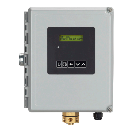
NX48 and NX51 NXT Stager Controller
Service Manual
TABLE OF CONTENTS
NXT STAGER DIMENSIONS .................................................2
SYSTEM DEFINITIONS .........................................................3
(SYSTEM 14-DEMAND) .........................................................4
TIMER DISPLAY FEATURES.................................................5
CABLES & CONNECTIONS ..................................................5
TIMER OPERATION ..............................................................6
MASTER PROGRAMMING MODE FLOW CHART ...............7
USER PROGRAMMING MODE FLOW CHART ....................9
DIAGNOSTIC PROGRAMMING MODE FLOW CHART ........9
PLUMBING DIAGRAMS .........................................................11
SOLENOID USE.....................................................................14
ASSEMBLY ............................................................................15
ASSEMBLY ............................................................................16
WIRING DIAGRAM 48/51ES STAGER CONTROLLER ........17
TROUBLESHOOTING ...........................................................18
SERVICE ASSEMBLIES ........................................................19
IMPORTANT PLEASE READ:
• The information, specifications and illustrations in this
manual are based on the latest information available
at the time of printing. The manufacturer reserves the
right to make changes at any time without notice.
• This manual is intended as a guide for service of the
controller only. System installation requires information
from a number of suppliers not known at the time of
control manufacture. This product should be installed
by a plumbing professional.
• This product must be installed in compliance with all
state and municipal plumbing and electrical codes.
Permits may be required at the time of installation.
• If daytime operating pressure exceeds 80 psi,
nighttime pressures may exceed pressure limits. A
pressure reducing valve must be installed if pressure
exceeds 125 psi.
• Do not install the unit where temperatures may drop
below 32°F (0°C) or above 110°F (43°C).
• Do not place the unit in direct sunlight. Black units will
absorb radiant heat increasing internal temperatures.
• Do not strike the controller or any of the components.
• Warranty of this product extends to manufacturing
defects. Misapplication of this product may result
in failure to properly condition water, or damage to
product.
• A prefilter should be used on installations in which free
solids are present.
• Correct and constant voltage must be supplied to the
controller to maintain proper function.
43037 Rev F
AU11
Advertisement
Table of Contents

Summary of Contents for AQmatic NX48
-
Page 1: Table Of Contents
NX48 and NX51 NXT Stager Controller Service Manual TABLE OF CONTENTS NXT STAGER DIMENSIONS ..........2 SYSTEM SPECIFICATIONS 48ES AND 51ES SERIES ..2 SYSTEM DEFINITIONS ............3 SYSTEM OPERATION IN SERVICE IMPORTANT PLEASE READ: (SYSTEM 14-DEMAND) ............4 • The information, specifications and illustrations in this TIMER DISPLAY FEATURES..........5 manual are based on the latest information available at the time of printing. -
Page 2: Nxt Stager Dimensions
NXT STAGER DIMENSIONS SYSTEM SPECIFICATIONS 48 AND 51 NXT SERIES 11.13 [282.7] 8.91 [226.3] Generic Meter Guidelines Optional Solenoid • Open collector output 10.50 [266.6] • Pulse rate generated must not exceed 100 pulses per second (100 Hz), or 6,000 pulses per minute •... -
Page 3: System Definitions
SYSTEM DEFINITIONS System System # of Type Service Outlet Valve Operation Discussion Number Description Tanks/ Controlled by... Controls Single Unit Time Clock: No Meter Stager Single tank configuration. During (no solenoid required) Regeneration no water available to service Immediate: One Meter unless optional bypass valve #2A installed. Delayed: One Meter Remote Signal Start: No Meter Interlocked... -
Page 4: System Operation In Service (System 14-Demand)
SYSTEM OPERATION IN SERVICE (SYSTEM 14-DEMAND) 5. The third tank returns to Standby as demand decreases The system operates as part of a multi-tank regeneration past the second trip point. system. This example applies to either a 2, 3 or 4 tank system. Each tank in the system will have an active flow meter input, even in Standby. -
Page 5: Timer Display Features
TIMER DISPLAY FEATURES NETWORK/COMMUNICATION CABLES & CONNECTIONS Valve State Display Screen (SBY, SRV, INI, LCK) Time of Day alternates with Error Screen Use a CAT5 Network/Communication cable. Valve Example: Valve #, Volume Address Connect the network/communication cable to either port before Remaining, Errors Flow System... -
Page 6: Timer Operation
TIMER OPERATION Remote Lockout Set Time of Day The timer does not allow the unit/system to go into Hold the Up or Down button to change time. While in time Regeneration until the regeneration lockout input signal to the change mode press Shift to adjust next digit over. On multiple unit is cleared. -
Page 7: Master Programming Mode Flow Chart
Range: 2 to 4 Valves in the System MASTER PROGRAMMING MODE FLOW NOTE: This screen will not display for System Type 4. CHART Example: REGEN TYPE: Time Clock Delayed (Default) TIME CLK DELAYED Before entering Master Programming, please CAUTION Options: Time Clock Delayed (System 4 Only) (Default) contact your local professional water dealer. - Page 8 MASTER PROGRAMMING MODE FLOW NOTE: Display will only appear on the master timer and it must be CHART continued programmed as valve position #1. Use the Shift button to move one space to the left. Example: NOTE: This screen will only display for System 14. Off (Default 51-09 Stager) CYCLE 5 OFF NOTE: This screen will only display when cycle 4 is not OFF.
-
Page 9: User Programming Mode Flow Chart
USER PROGRAMMING MODE FLOW DIAGNOSTIC PROGRAMMING MODE CHART FLOW CHART Entering User Programming Mode Entering Diagnostic Programming Mode Hold the Up and Down buttons for 5 seconds. 1. Push and release the "D" button. 2. Press the Extra Cycle button once per display until all displays are viewed and Normal Display is resumed. - Page 10 NXT Stager Controller AU11...
-
Page 11: Plumbing Diagrams
PLUMBING DIAGRAMS Stager Operation 4 Position Softener (48-00 Stager) Stagers are motor driven, rotary multi-port valves used to control a set of valves in a predefined sequence. They function by internally connecting inlet pressure to a defined set of control ports and allowing other control ports be vented through a drain. Control ports are used to open and close valves in a preset sequence. - Page 12 PLUMBING DIAGRAMS continued 4 Position Filter (48-00 Stager) 5 Position Softener w/Timed Brine Refill (51-06 Stager) Optional Hard Water Bypass Valve Drain Line Flow Control not shown 4 POSITION FILTER Installer to plug (with PN1071903)for lter operation Note A: All valves normally open except optional valve 2A. Note B: Inverted Stager types will have these ports pressurized.
- Page 13 PLUMBING DIAGRAMS continued Multiple Tank 4 Position Softener (48-00 Stager) EJECTOR RAW WATER BRINE To Additional Tanks INLET As Required SERVICE UNIT A UNIT B DRAIN LINE FLOW DRAIN CONTROL NOT SHOWN NOTE: All valves normally open, pressure to close. NOTE: Valve 2 for each tank is controlled by solenoid for system 7, 9, 14 Multiple Tank 5 Position Softener (51-06 Stager)
-
Page 14: Solenoid Use
SOLENOID USE Solenoids only required for Systems 7, 9 and 14 Series 48-00/51-09 Stager Installer to Drain Plug Port 2 Solenoid Valve Inlet Pressure Flow Flow Solenoid Energized Solenoid De-energized Energized To Close The NXT Stager control can operate an optional 24 VAC solenoid to control when a tank is off line. This solenoid is electrically connected to the "lower drive"... -
Page 15: Stager Controller, 48Es, Nema 4 24V/50-60Hz Assembly
STAGER CONTROLLER, 51 & 48, NXT, NEMA 4 24V/50-60Hz ASSEMBLY Service Parts Common To Both 48 & 51 NXT Stager Control 61783......Kit, 48/51 ES NEMA4, Solenoid 61784......Kit 48/51 ES, 3214 NXT, CKT Board & Keypad 61764......Cable Assy, Communication, CAT 5, 5 Meters Long 1075499......Switch, Micro 40941......Wire Harness, Upper Drive... -
Page 16: Stager Controller, 51Es, Nema 4 24V/50-60Hz Assembly
WIRING DIAGRAM 48/51 NXT STAGER CONTROLLER NXT Stager Controller AU11... -
Page 17: Troubleshooting
TROUBLESHOOTING Detected Errors If a communication error is detected, an Error Screen will alternate with the main (time of day) screen every few seconds. • All units In Service remain in the In Service position. • All units in Standby go to In Service. •... - Page 18 © 2016 AQ Matic Valve and Controls Company, Inc. All rights reserved. All AQ Matic trademarks and logos are owned by AQ Matic or its affiliates. All other registered and unregistered trademarks and logos are the property of their respective owners. Because we are continuously improving our products and services, AQ Matic reserves the right to change specifications without prior notice.
Need help?
Do you have a question about the NX48 and is the answer not in the manual?
Questions and answers