
Subscribe to Our Youtube Channel
Summary of Contents for Securakey SURE-FI SK-DS004-WIEGAND
- Page 1 Sure-Fi Wiegand Bridge Operators Manual Doc #P10226 Rev 1.9 www.SecuraKeyStore.com | (800) 878-7829 | Sales@SecuraKeyStore.com...
- Page 2 Sure-Fi Wiegand Bridge Quick Startup: The two units that are packaged together (banded) are factory paired and will only communicate with each other. Check initial operation Connect the 9V battery (included) to the 9V power cable (included) and plug the two-position connector in to the Wiegand Controller / Remote Interfaces at the ‘12V’...
-
Page 3: Table Of Contents
Sure-Fi Wiegand Bridge Table of Contents Part Numbers Pg. 5 Product Overview Pg. 5 Features Pg. 5 General Specifications Pg. 6 Radio Transceiver Specifications Pg. 6 Device Overview Pg. 7 Controller Interface – Top & Bottom Connector pin descriptions Pg. 8 Remote Interface –... - Page 4 Sure-Fi Wiegand Bridge Figure Reference Guide Figure 1: Device Overview Pg. 7 Figure 2: Connecting Power and Backup Battery Pg. 10 Pg. 12 Figure 3: Jumpers JP1/JP2 Figure 4: Diagram of Power Input, +VBUS, and JP1/JP2 functionality Pg. 12 Figure 5: Chain multiple systems, wiring diagram Pg.
-
Page 5: Part Numbers
Sure-Fi Wiegand Bridge Part Numbers DS004-BRIDGE Wiegand Bridge system: includes 1 ea. DS004-CONTROLLER and DS004-REMOTE DS004- Wiegand Controller Interface CONTROLLER Wiegand Remote Interface Note: if the product part number includes ‘REV2’ such as ‘DS004-REMOTE DS004- REV2’, then the relays are solid state type with the specifications noted on REMOTE page 6. -
Page 6: General Specifications
Sure-Fi Wiegand Bridge General Specifications Operating Voltage: 12VDC (9VDC to 15VDC) Operating Current: @ 12VDC: 0.08A (idle), 0.3A (transmit) Operating Power: 3.6 Watt (peak) Battery backup: 12V sealed lead acid (SLA) type only (not included) Battery Low Threshold: < 11VDC Battery Charge Voltage: 13.75V maximum at standby charge Battery Charge Current:... -
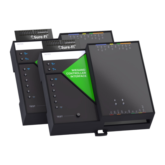
Page 7: Device Overview
Sure-Fi Wiegand Bridge Device Overview Figure 1: Device Overview www.SecuraKeyStore.com | (800) 878-7829 | Sales@SecuraKeyStore.com... -
Page 8: Controller Interface - Top & Bottom Connector Pin Descriptions
Sure-Fi Wiegand Bridge Controller Interface - Top connector Table 1: Position Description 1 (right) R4 NC: Relay 4 Normally-Closed terminal R4 COM: Relay 4 Common terminal R4 NO: Relay 4 Normally-Open terminal R2 IN: Relay 2 control: activates Relay 2 on Remote unit GND: - DC Ground R1 IN: Relay 1 control: activates Relay 1 on Remote... -
Page 9: Remote Interface - Top & Bottom Connector Pin Descriptions
Sure-Fi Wiegand Bridge Remote Interface - Top connector Table 3: Position Description 1 (right) R2 NC: Relay 2 Normally-Closed terminal R2 COM: Relay 2 Common terminal R2 NO: Relay 2 Normally-Open terminal R4 IN: Relay 4 control: activates Relay 4 on Controller unit GND: - DC input R3 IN: Relay 3 control: activates Relay 3 on... -
Page 10: Providing Power To The Controller And Remote Interfaces
Sure-Fi Wiegand Bridge Providing Power Each unit requires a 12VDC supply that can source at least 0.5A, but a 1A supply is always recommended to ensure adequate power. If a Maglock, Door Strike, or other device is to be powered through an on-board wet relay, then the additional power required for those devices will need to be considered when selecting a power supply. -
Page 11: Power Led And Battery Led Diagnostics
Sure-Fi Wiegand Bridge Power and Battery LED Diagnostics/Flash codes The two green LED’s that are labeled ‘POWER’ and ‘BATTERY’ are used to provide the status of the 12VDC input power and the Battery input voltage. The LED status information is described here: Power Status: POWER LED LED STATE DESCRIPTION... -
Page 12: Jumpers Jp1 And Jp2 (Remote Interface Only)
Sure-Fi Wiegand Bridge Jumpers JP1 and JP2 (REMOTE INTERFACE ONLY) Jumpers JP1 / JP2 are used to connect the relay COM terminal to either GND or +VBUS. Connecting the jumper to the +VBUS creates a wet relay contact that can be used to source power to a device. -
Page 13: Relays
Sure-Fi Wiegand Bridge Relays Operating the relays The relay outputs are operated by the corresponding relay inputs that are on the paired unit. For example, to activate Relay 1 on the Remote Interface, the Relay 1 input (R1 IN) on the Controller Interface must be shorted to ground (0VDC) using either a dry relay contact, a switch, or a digital voltage 0 to 5VDC interface. -
Page 14: Auxiliary (Aux In / Aux Out)
Sure-Fi Wiegand Bridge Auxiliary Input/Output (AUX IN / AUX OUT) The Auxiliary input AUX-IN on the Remote Interface corresponds with the Auxiliary output AUX OUT on the Controller Interface. The AUX IN is interfaced in the same way as the Relay inputs, by shorting it to GND (0VDC) using either a dry relay contact, a switch, or a digital voltage 0 to 5VDC interface. -
Page 15: Chain Multiple System Pairs For Extended Range
Sure-Fi Wiegand Bridge Chain multiple system pairs for extended range If a single paired system is unable to communicate from the desired two endpoints, a second paired system can be used to create a ‘chain’ to extend the range. If required, many paired systems can be ‘chained’... -
Page 16: Mounting
Sure-Fi Wiegand Bridge Mounting DIN Rail mount DIN rail mounting allows the unit to easily clip and unclip from the DIN rail. Attach a piece (minimum 4” length) of 35mm type DIN rail to the wall and then snap the unit to the DIN rail or slide it on from the end. - Page 17 Sure-Fi Wiegand Bridge The top screw is shown mounted through the DIN clip to the wall: Figure 7: The bottom screw is shown mounted through the black DIN clip to the wall: Figure 8: www.SecuraKeyStore.com | (800) 878-7829 | Sales@SecuraKeyStore.com...
-
Page 18: Sure-Fi App - Downloading, Installing, Connecting
Sure-Fi Wiegand Bridge Sure-Fi APP The Sure-Fi APP for iOS and Android allows for firmware updates, configuration and customization as well as for some diagnostics and troubleshooting information. The APP is continually being updated to provide for more information and features and to improve its ease of use. To download, search for ‘Sure-Fi’... -
Page 19: Sure-Fi App - Changing The Name Of The Unit, Configuration Of The Wiegand
Sure-Fi Wiegand Bridge ‘Update Firmware’ from the menu. The ‘Update Firmware’ screen will show the current firmware versions and show if a newer released version is available. Select ‘Start Firmware Update” to begin the updating process. A notification will be given when the update is complete. Change the name of the unit On the main screen, tap the ‘edit’... - Page 20 Sure-Fi Wiegand Bridge 1. Wire the Wiegand outputs (D0, D1, GND) from the Wiegand Controller Interface to the Access Panel. 2. Wire the Wiegand device to the Wiegand Remote Interface and ensure that the Wiegand device is powered per the manufacturer’s specification. 3.
-
Page 21: Wiring Examples
Sure-Fi Wiegand Bridge Wiring a Wiegand Device Figure 9: Wiring a Wiegand device to the Remote Interface Figure 10: Wiring the Panel Wiegand port (and R1 IN & GND for dual LED, if required) to the Wiegand Controller Interface www.SecuraKeyStore.com | (800) 878-7829 | Sales@SecuraKeyStore.com... - Page 22 Sure-Fi Wiegand Bridge Wiring a Mag-Lock that is powered with a relay wet contact Figure 11: Wiring a Maglock to Relay 1 NC as a wet contact on the Remote Interface Figure 12: Wiring the Panel Door output relay to R1 IN & GND on the Controller Interface www.SecuraKeyStore.com | (800) 878-7829 | Sales@SecuraKeyStore.com...
- Page 23 Sure-Fi Wiegand Bridge Wiring example for a Door Position Sensor Figure 13: Wiring a Door Position Sensor to R3 IN on the Remote Interface Figure 14: Wiring the Panel Door Monitor Input to R3 NO & R3 COM on the Controller Interface www.SecuraKeyStore.com | (800) 878-7829 | Sales@SecuraKeyStore.com...
- Page 24 Sure-Fi Wiegand Bridge RELAY 4 IN Remote Interface / RELAY 4 OUT Controller Interface Figure 15: Relay 4 IN wiring a Request to Exit button on the Remote Interface Figure 16: Relay 4 OUT Wiring at the Controller Interface www.SecuraKeyStore.com | (800) 878-7829 | Sales@SecuraKeyStore.com...
- Page 25 Sure-Fi Wiegand Bridge Wiring a Door-Strike and a REX push button Figure 17: REMOTE wiring of an externally powered Door-Strike (R1 NO), REX button (R4 IN), and Wiegand Figure 18: PANEL wiring for the Door Strike control (R1 IN), REX button (R4 NO), and Wiegand device www.SecuraKeyStore.com | (800) 878-7829 | Sales@SecuraKeyStore.com...
- Page 26 Sure-Fi Wiegand Bridge Wiring Example for Mag-Lock Figure 19: REMOTE wiring for an externally powered Maglock (R1 NC), REX button (R4 IN), and Wiegand Figure 20: PANEL wiring for an externally powered Maglock (R1 IN), REX button (R4 NO), and Wiegand www.SecuraKeyStore.com | (800) 878-7829 | Sales@SecuraKeyStore.com...
- Page 27 Sure-Fi Wiegand Bridge Wiring example for Gate Operator, REX, and Wiegand Figure 21: REMOTE wiring for a Gate Operator (R1 NO), REX button (R4 IN), and Wiegand device Figure 22: PANEL wiring for a Gate Operator (R1 IN), REX button (R4 NO), and Wiegand device www.SecuraKeyStore.com | (800) 878-7829 | Sales@SecuraKeyStore.com...
-
Page 28: Fcc And Industry Canada Regulatory Statements
Sure-Fi Wiegand Bridge FCC and Industry Canada Regulatory Statements This device complies with part 15 of the FCC rules. Operation is subject to the following two conditions: (1) This device may not cause harmful interference, and (2) this device must accept any interference received, including interference that may cause undesired operation. -
Page 29: Warranty
Sure-Fi Wiegand Bridge FCC Radiation Exposure Statement This equipment complies with FCC radiation exposure limits set forth for an uncontrolled environment. This equipment should be installed and operated with minimum distance 20cm between the radiator and your body. Important Note: Radiation Exposure Statement: This equipment complies with IC radiation exposure limits set forth for an uncontrolled environment.
Need help?
Do you have a question about the SURE-FI SK-DS004-WIEGAND and is the answer not in the manual?
Questions and answers