
Subscribe to Our Youtube Channel
Related Manuals for Nikrans NS-150GD


Summary of Contents for Nikrans NS-150GD
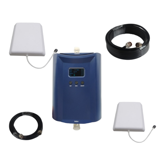
- Page 1 WWW.MOBILE-SIGNAL-BOOSTERS.SHOP INSTALLATION GUIDE PHONE SIGNAL BOOSTER Nikrans NS-150GD Freq.: 900, 1800 MHz Coverage: 1700 ft²...
-
Page 2: Safety Warnings
PREFACE This user’s manual describes the installation and maintenance of wide band consumer boosters. Please do read user manual carefully before installing and maintaining repeaters. The information in this manual is subject to change without prior notice. 1. SAFETY WARNINGS Users must follow the principles below? Repeater should follow system requirements;... - Page 3 2. INTRODUCTION AND REASONS FOR WEAK CELLULAR SIGNALS Mobile Signal Booster is a perfect solution for providing improvement of cellular signal reception inside a house, office, restaurant, VIP Room, apartment, building or shopping mall. Generally cell phones cannot pick up or maintain a strong cellular signal due to one of the two following reasons: 1.
-
Page 4: Model Description
3. MODEL DESCRIPTION Nikrans NS-150GD Dual Band GSM repeater is the answer to poor network coverage. Operating at two frequencies, 900MHz and 1800MHz, it mainly amplifies signal strength for GSM voice calls and 3G connection though it may be efficient for amelioration of 4G signal so long as the latter is transmitted at 1800 MHz in the customer's area. It is compatible with all major carriers in the UK, i.e. -
Page 5: Specification
4. SPECIFICATION Indoor coverage: 1700 ft² Up-link freq: 880-915MHz & 1710-1785 MHz Down-link freq: 925-960MHz & 1805-1880 MHz Up-link Gain: 60 dB Down-link Gain: 60 dB Power supply: Input AC100~240V,output DC7V/3A Working t °C: -25/+55 Humidity: 5 - 85 % Size (mm): 175*131*33mm Booster Weight:... - Page 6 5. REPEATER SYSTEM OVERVIEW The picture below shows how simple and fast booster installation is and how effectively it works. A Yaggi or panel antenna (it depends on the booster model and its power), as donor/outdoor antenna, is installed at the top of the roof to pick up good mobile signals from the base station, and sends them through the cable to the booster where the signals get amplified significantly;...
-
Page 8: Outdoor Antenna Installation
6. ANTENNAS AND CABLES SETTING UP 6.1. Outdoor antenna installation The repeater’s main function is to improve weak RF signals in an area. The formula is: Input power + Gain= Output power. The signal strength from an outdoor antenna directly affects the efficiency of the indoor coverage. It is very important to choose the correct outdoor antenna location in order to get the best signal. -
Page 9: Indoor Antenna Installation
Installation of a panel antenna as an outdoor antenna Installation of Yagi wide band antenna as an outdoor antenna Installation of a Yaggi antenna as an outdoor antenna Cable layout and connector assembly 1. Keep the type, specifications, routing direction, location and curvature radius of cables in compliance with the model requirements. - Page 10 1. Omni antenna (ceiling Omni or whip antenna) shall be installed in the center and radiate all directions. 2. It is better to use a directional panel antenna or Yaggi antenna when the area shape is long and narrow (corridors, long row of houses in two sides, tunnels or elevators or rural open space). Requirements to indoor antenna installation: •...
-
Page 11: Repeater Installation
7. REPEATER INSTALLATION 7.1 Installation requirements 7.1.1 Installation Location Requirements 1. The repeater shall be installed indoor in a cool, dry and ventilated room without erosive gas or smoke, or on a cool and ventilated wall to ensure excellent heat dissipation. 2. - Page 12 INSTALLATION STEPS 1. Find an appropriate position for an outdoor antenna. ( see the r equirements in 6.1. sect. ) 2. Plug in the outdoor antenna to the mobile booster from BS side and fasten tightly. 3. Plug in the indoor antenna to the mobile booster from MS side and fasten tightly. 4.
-
Page 13: Repeater Settings
7.2.2 Repeater’s ports description 1. Outdoor port: connected with the outdoor antenna by cable 2. Indoor port: connected with indoor antenna directly or by cable 3. DC IN: connected with power supply. 7.2.3 Accessories selection Choosing accessories pay attention to the two characteristics – frequency and impedance. All accessories shall support the repeater’s frequencies. -
Page 14: Manual Gain Control (Mgc)
Status ALARM It is working in linearity Green Warning: Input signals may be not enough, so please check on coverage effect, do not do anything if it is good coverage; otherwise please adjust the repeater system to get better coverage. A little bit stronger input signals or slight self oscillation have occurred. - Page 15 DIP switch uplink attenuation setting: 0 dB 5 dB 10 dB 15dB For single system plastic closet? Turn ON the dip switches to reduce gain as follows: Put ON a pair of switches for a total of 15dB reduction in gain. (DL1 &...
- Page 16 Put ON a pair of switches for a total of 15dB reduction in gain. (DL1 & UL1 – Alarm Low) – For 800MHz or 900 MHz Band (DL2 & UL2 – Alarm High) – For 1700, 1800, 1900 & 2100 MHz Band For dual system plastic closet? Turn ON the dip switches to reduce power as follows: Put ON a pair of switches for a total of 15dB reduction in gain.
-
Page 17: Repeater Commissioning
Repeater Commissioning Downlink gain setting First the alarm LED only indicates the downlink input power level, here we use color of Alarm LED to adjust the gain of the repeater. Alarm LED color must remain green. As for the downlink working performance, it is a good working point that Alarm LED maintains “Green”... -
Page 18: System Test
other, it will evoke self-excitation. To fix the problem, you would need to place the outdoor antenna at the largest possible distance from the indoor antenna. 7.4. System Test 7.4.1. Check whether the coverage is good 1. Take a test with a mobile phone or a data card (engineering mobile phone is preferred). To test signal level with a cell phone, make use of its engineering mode (Field Test Mode), which is an application available in free access or a phone mode requiring no extra setups. - Page 19 For maximum precision in signal level testing, switch your cell phone into Field Test Mode and see dB parameter. The closer dB signal level to 0, the better cell phone reception you’ll get. • -105 to -100 = Bad/drop call •...
- Page 20 8. FAQ 1. Will booster increase the RF radiation? No, it will decrease instead. Every cell phone irradiates heavily being in zones with poor mobile signal as a cell phone is constantly in searching mode. The danger is your cell phone is about 2cm to your body, which makes its usage rather harmful. And when a booster is installed, it improves the mobile signals in the coverage, and your cell phone stops irradiating strongly, thus it will reduce the RF radiation of the mobile phone tremendously.
- Page 21 Nikrans product development process is rigorously assessed to comply with ISO 9001:2008 standard and implicates internal tests, which greatly ensures the quality of our goods. High product quality is also confirmed by Phoenix Testlab, Germany and is proved with CE and RoHS certificates. That’s why a 3-year warranty applies to any of Nikrans boosters.
- Page 22 Certificates Hereby, Nikrans declares that this signal booster is in compliance with the essential requirements and other relevant provisions of Radio Equipment Directive (RED) 2014/53/UE (CE marking). info@mobile-signal-boosters.shop · +448000698689 (Sales) · www.mobile-signal-boosters.shop...
Need help?
Do you have a question about the NS-150GD and is the answer not in the manual?
Questions and answers