Table of Contents
Advertisement
Quick Links
Advertisement
Table of Contents

Summary of Contents for LYINTL H-F16/2
- Page 1 OWNER'S MANUAL PROFESSIONAL MIXER...
-
Page 2: Table Of Contents
Index Before operating,please read this manual completely. Specifications ..........1 Input Module. -
Page 3: Input Module
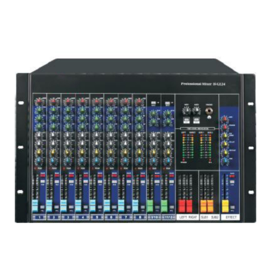
Input Module 1. MIC These are to be connected with microphone XLR jack are used for the balancedd signal. +48V phantom power available on each input Mic socket. 2. LINE The unbalanced mic input is provided for the use of a unbalancedd mic and is designed to accept a unbalanced high impedance input signal. - Page 4 Input Module The control has shelving response that giving 15dB of boost or Cut at 80Hz. Adding warmth to vocals or extra punch to guitars. drums and synths but turn to the right, turn to the left to reduce stage rumble, hum or to improve a mushy sound.
- Page 5 Input Module 10. MAIN This switch routes signal form the channel to the stereo masters. The relative amounts of signal sent to the left and right is determined by the position of the PAN pot. When the switch is depressed signal from the channel is sent to masters.
-
Page 6: Stereo Input Module
Stereo Input Module 14. L /R PIN JACK This used for connection into line level equipment. (Tape machines etc.) L/R STEREO INPUT These light impedance inputs accept 2-pole phone jacks. Use these inputs for keyboards, drum machines, synths, tape machine or processing units, if the source signal is mono please plugs into the left channel socket only. -
Page 7: Master Section
Master Section 17. AUX1 AUX2 This rotary control adjusts the level of signal sent for, the auxiliary bus to the auxiliary output. For optimum performance this should be set to around 7or 8 on the scale, and the input level often effects unit being fed from the aux output should be adjusted to operate with this level of signal. -
Page 8: Effect
Effect 22. AUX TAPE LEVEL You con adjust the volume of AUX IN or PLAY signal by this when connecting AUX IN or PLAY. 23. PHONE LEVEL This rotary fader controls the output level to the control room and headphone. 24. - Page 9 THE LEVEL INDICATOR The meter pod hoses the four level meters together with the AFL/PFL indicator LED and the power supply status indicators. 32. Operating levels Output levels should adjust so that signals average 0dB on the meters, and peak at +3dB.
-
Page 10: Output Connectors
Output Connectors 37. BALANCED OUTPUT (MAIN L/R) These sockets send line level signals from the mixer to external devices (for example: EQ or power amplifier). L/R IACK UNBALANCEDD OUTPUT These are jacks to send the finally mixed outputs to the other appliance (amplifier or EQ). -
Page 11: Power
47. POWER SUPPLY INPUT SOCKET Connect the power supply unit to this socket. Make sure the power supply unit is not plugged into mains before connecting to the mixer. 48. POWER ON/OFF SWITCH This switch turn on and off the power of the unit. Rear Panel 1. -
Page 12: System Connection
Unbalanced AUX audio signal output of SUB2 8. AUX 2 AUX2 audio signal output 9. AUX 1 AUX1 audio signal output 10. AUX 1 AUX audio signal input 11. Phone Audio signal output for monitor headphone 12-13. REC1/2 Recording stereo signal output 14. - Page 13 2. Connection of headset jack 3. Balanced input connection...
- Page 14 4. Different type of connector Note: If balanced(TRS) jack connect to unbalanced (TS) jack, hot (+) terminal can not connect to cold (-) terminal.
-
Page 15: Usually Set Up
Usually Set Up Even if you do not like to read manual, please read this section. This procedure is very important, even if you do not like to read manual. Please read this section. After you connected up the system, you are ready to set the initial set up for every input channel, the matching of every input trim to the signal source is crucial. -
Page 16: System Diagram
System Diagram Safety Precautions CAUTION: TO REDUCE THE RISK OF ELECTRIC SHOCK.DO NOT REMOVE COVER (OR BACK).NO USER SERVICEABLE PARTS INSIDE.REFER ALL SERVICING TO QUALIFIED SERVICE PERSONNEL. Keep this mixer away from dust anti dirty environment:cover the unit whit not in use.Using a soft dry brush anti occasional wipe with a damp cloth, do not use any other solvents, which may cause damage to paint or plastic parts.
Need help?
Do you have a question about the H-F16/2 and is the answer not in the manual?
Questions and answers