
Summary of Contents for Wheatstone Corporation L-8
- Page 1 L - 8 Modular Control Surface TECHNICAL MANUAL 600 Industrial Drive, New Bern, North Carolina, USA 28562...
- Page 2 L - 8 Modular Control Surface Technical Manual ©2013 Wheatstone Corporation WHEATSTONE CORPORATION 600 Industrial Drive New Bern, North Carolina 28562 tel 252-638-7000 / fax 252-637-1285 L-8 / Sep 2013...
- Page 3 The Wheatstone L-12 and L-16 are a 12- and 16-fader version of the L-8 control surface. The L-12/L-16 is powered by a Wheatstone Model PSE-L rackmount power supply (see next page for details). Other then the physical dimensions and two extra slots for the Accessory panels, all other aspects of the L-12/L-16 are the same as the L-8.
- Page 4 Power and Ethernet Connections The L-12/L-16 control surface is powered by a Wheatstone Model PSE-L rackmount power supply. This unit occupies a single 19" wide rack space. Note the power supply should be mounted in an equipment rack within fifteen feet of the control surface.
- Page 5 Note each power supply is fitted with a 3-wire grounded AC cord that The power feed recom- should be plugged into a “clean” AC power source, that is, an AC source mended in the text is often that feeds only the control room audio gear. This source should be a separate installed and referred to in studios as an “isolated AC feed from those powering lighting, air-conditioning, or any other non-audio...
- Page 6 Attention! PSE-L Power Supply Important Safety Instructions 1. Read these instructions. 2. Keep these instructions. 3. Heed all warnings. 4. Follow all instructions. 5. This equipment must be installed and operated in a dry location free from dripping or splashing liquids. No objects filled with liquid (such as beverage containers and the like) shall be placed on or near the unit.
- Page 7 Attention! PSE-L Alimentation Consignes De Sécurité Importantes 1. Lire ces instructions. 2. Conserver ces instructions. 3. Observer tous les avertissements. 4. Suivre toutes les instructions. 5. Ce matériel doit être installé et utilisé dans un endroit sec à l'abri d'éclaboussures de liquides ou de gouttes.
- Page 8 This equipment must be installed and wired properly in order to assure compliance with FCC regulations. Caution! Any modifications not expressly approved in writing by Wheatstone could void the user's authority to operate this equipment. L-8 & L-12 / Sep 2014...
- Page 9 Adding The L-8/L-12 To The Peripheral Devices* Tab NOTE: For the L-8 / L-12 control surface software versions after v. 1.4.6 the following procedure is no longer needed and should not be performed. In order to utilize all the features of the L-8/L-12 control...
-
Page 10: Table Of Contents
GUI Menu Summary ..............2-16 Control Surface Menus ..............2-17 Network........................2-17 Blade.........................2-17 Versions........................2-17 Exit Menu ........................2-18 Chapter 3 - L-8 Controls and Functions Input Module (L8-IN) ..............3-2 Input Sources ......................3-2 Soft Button .........................3-3 Assign Switches ......................3-3 The UTIL Bus ......................3-3 Display ........................3-3... - Page 11 Chapter 5 - Host CPU (HC-L8) Overview..................5-2 Ethernet IP Addressing ............. 5-2 Ethernet Interface Wiring .............. 5-2 Hook-Ups ..................5-3 “CT4” RJ-45 - Main Ethernet Connector ..............5-3 Typical Ethernet Cable ....................5-3 page Contents – 2 L-8 / Sep 2013 L-8 / Dec 2016...
- Page 12 C O N T E N T S Appendices Appendix 1 Replacement Parts List ..............A-3 Appendix 2 Configuring L-8 for Use in WheatNet-IP Systems .......A-6 page Contents – 3 L-8 / Sep 2013 L-8 / Dec 2016...
-
Page 13: Chapter 1 - General Information
G E N E R A L I N F O R M A T I O N General Information Chapter Contents Introduction ..................1-2 Control Surface Placement ............1-3 Power Supply and Ethernet Connections ........1-4 page 1 – 1 L-8 / Sep 2013... -
Page 14: Introduction
Snapshots of the L- 8’s configuration can be saved and recalled at the touch of a button, making setup for different working sessions a snap. page 1 – 2 L-8 / Sep 2013... -
Page 15: Control Surface Placement
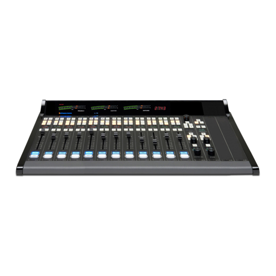
Control Surface Placement The L-8 modular control surface is designed for countertop place- NOTE: This console ment. The L-8 is a sleek, versatile, and low profile control surface. Avoid contains static-sensi- tive devices. Normal proximity to any electromagnetic fields, such as large power transformers, precautions against motors, and fluorescent lighting fixtures. -
Page 16: Power Supply And Ethernet Connections
G E N E R A L I N F O R M A T I O N Power and Ethernet Connections The L-8 control surface is powered up through the WheatNet-IP 88cbl Console BLADE. The power and Ethernet connectors are mounted on the Host Controller card (HC-L8 PCB) located behind the control surface’s rear panel. - Page 17 VDips Tab ........................2-10 Monitor Config Tab ....................2-13 Buttons Tab .......................2-14 Visibilities Tab ......................2-15 GUI Menu Summary ..............2-16 Control Surface Menus ..............2-17 Network........................2-17 Blade.........................2-17 Versions........................2-17 Exit Menu ........................2-18 page 2 – 1 L-8 / Sep 2013...
-
Page 18: Getting Started
WheatNet-IP 88cbl audio Console BLADE 3. Note that the Console BLADE 3 must be connected to a Gigabit port on a switch. It cannot be connected directly to the L-8 because the L-8 port is not Gigabit. A powerful 1RU device containing the console’s digital signal processing, input, output, and logic circuitry, the engine has no fans and may be located either next to the control surface or at a remote location. -
Page 19: Tabbed Navigation
L-8 GUI has been configured to communicate with. Click Add... to add a device to the list, Edit... to change the name of an L-8 or give the GUI a different IP address to talk to it on, or Remove to delete the device currently highlighted in the list. To the right of these buttons is the Online check box, which is used to toggle the GUI connection to the highlighted device between online (checked) and offline (not checked). -
Page 20: System Info Tab
S U R F A C E C O N F I G U R A T I O N System Info Tab When you first start the L-8 GUI there will be no information showing in the System Info Pane. Assuming that you are connected to a working system, you can get this pane to fill by selecting WheatNet‑IP System>System Scan... - Page 21 If you have changed configuration in regard to Blades present or signals defined and their names since last saving the scan information you should rescan and resave. page 2 – 5 L-8 / Sep 2013...
-
Page 22: Engine Tab
Studio Tallies 2 on the VDips tab is turned on. If 1 and 2 are both checked here then a signal that uses Studio Tallies 1 or 2 on a fader that is ON will cause the ON AIR to light. page 2 – 6 L-8 / Sep 2013 L-8 / Jan 2015 L-8 / Dec 2016... - Page 23 0 is also allowed and is used to turn off the screen saver mode. Timer Display Format – The time of day is shown on the L-8 and can be shown in 12-hour format or 24-hour format. The default format is 12-hour. To change to 24-hour format, check the 24 hours check box.
-
Page 24: Talent Access Tab
• If Allow PGM Bus Assign is not checked, the operator will not be able to use the PGM ASSIGN button to change any fader’s feed status to the PGM bus. • If Allow AUD Bus Assign is not checked, the operator will not be able to use the page 2 – 8 L-8 / Sep 2013... - Page 25 AUX ASSIGN button to change any fader’s feed status to the AUX bus. • If Allow OL Bus Assign is not checked, the operator will not be able to use the UTIL ASSIGN button to change any fader’s feed status to the UTIL bus. page 2 – 9 L-8 / Sep 2013...
-
Page 26: Vdips Tab
When the L-8 GUI is first started, the VDips tab Signals list contains only one item, Default. If you select Default you will be editing the VDip settings of all sources in the system, except those you have specifically overridden. - Page 27 Fader Cue – Assigns the signal to the Cue bus when the fader is moved all the way down. The CUE button can still be used to change the CUE status. page 2 – 11 L-8 / Sep 2013...
- Page 28 This is true when the fader is turned on. It also true when the fader is turned off, unless the OL Off Line box is checked (above). This setting will have no effect on any fader where the Bus Minus Direct Out box is checked (above). page 2 – 12 L-8 / Sep 2013...
-
Page 29: Monitor Config Tab
Cancel, which will cancel any changes you made since entering the Monitor Config tab, or since you last clicked Apply. page 2 – 13 L-8 / Sep 2013... -
Page 30: Buttons Tab
None there will be additional configuration, needed to complete the desired functionality, that must be done in the optional Navigator software. Refer to the WheatNet‑IP Audio Over IP Network manual for details. page 2 – 14 L-8 / Sep 2013... -
Page 31: Visibilities Tab
2-4 you will not see all the sources that are available to the L-8. Scroll up and down the Channel list, check or un- check signals as desired for that channel, and click the Ap‑... -
Page 32: Gui Menu Summary
• Exit – Used to exit the L-8 GUI View – the View menu is used to show or hide certain sections of the L-8 GUI or to change the GUI appearance: • Devices – Used to show or hide the Devices Pane (see page 2-3) •... -
Page 33: Control Surface Menus
FUNCTION knob enters the Blade... sub-menu, which provides the following choices: • Blade IP – this item allows you to view the IP address of the L-8’s host BLADE – dobby the FUNCTION knob and you can edit this address •... -
Page 34: Exit Menu
Turning the FUNCTION knob until Exit Menu is highlighted and dobbying the FUNCTION knob exits from the control surface menu. If you have the menu dis- played and are idle, not turning or pressing anything, for about 20 seconds, the L-8 will automatically exit from the menu. - Page 35 L - 8 C O N T R O L S A N D F U N C T I O N S L-8 Controls and Functions Chapter Contents Input Module (L8-IN) ..............3-2 Input Sources ......................3-2 Soft Button .........................3-3 Assign Switches ......................3-3...
-
Page 36: Input Module (L8-In)
L - 8 C O N T R O L S A N D F U N C T I O N S L-8 Controls and Functions Input Module (L8-IN) Input Sources The A/B/SET button on the L8‑IN input module (channel) is used for selecting the audio source for the channel. -
Page 37: Soft Button
Studio Tallies. The purpose of this icon is to indicate whether there any live microphones in the studio. When there is a live microphone, the icon will be red instead of gray if so programmed. page 3 – 3 L-8 / Sep 2013... -
Page 38: Tb Switch
Channel output level is set by a 100mm, professional, conductive plastic linear fader. Channel ON Switch The channel ON switch turns the channel signal ON and fires any chan‑ nel ON (START) logic mapped to the fader’s source signal. The switch page 3 – 4 L-8 / Sep 2013... -
Page 39: Channel Off Switch
The channel OFF switch turns the channel signal OFF and fires any chan‑ nel OFF (STOP) logic mapped to the fader’s source signal. The switch LED lights to indicate the channel is OFF. page 3 – 5 L-8 / Sep 2013... -
Page 40: Control Room Module (L8-Cr)
Press and hold the input channel A/B/SET button until it begins to flash, then press the PAN button. When the PAN button is pressed the FUNCTION knob acts as a panpot in MONO, LEFT only, and RIGHT only modes, and page 3 – 6 L-8 / Sep 2013... -
Page 41: Mode Button
Event is recalled, except for any channels that are on at the time of recall. User access privileges may be configured to limit access to Save and/or Take Events in the Talent Access tab of the Wheatnet IP L8 Tool GUI. page 3 – 7 L-8 / Sep 2013... -
Page 42: Source Select Switches
The headphone output signal appears at the HEADPHONE JACK, located on the right side of the control surface. The jack is provided as a place to plug in user‑supplied stereo headphones having an impedance of 60 Ohms or higher. page 3 – 8 L-8 / Sep 2013... -
Page 43: Split Cue Button
In the event that you need to discuss an issue with Wheatstone Technical Support you may be asked for some or all of information shown in this display. This feature is discussed in greater detail in the Control Surface Menus section of Chapter 2. page 3 – 9 L-8 / Sep 2013... -
Page 44: Studio Control Module (L8-Sc)
The CUE master level control determines the overall loudness of the cue signal. There are two horizontal lines at the bottom of the INFO display. The top line indicates the volume level of the cue signal. page 3 – 10 L-8 / Sep 2013... -
Page 45: Studio Level Control
VU meter pairs (PROGRAM, AUDITION, and SWITCHED) are stereo LED bargraph type meters. The level of the signal being metered is indicated by the number of display elements that are lighted. The more elements lighted, the stronger is the sig‑ page 3 – 11 L-8 / Sep 2013... -
Page 46: Meter Select Button
‑ if the timer is already stopped, pressing and holding this button for three seconds will reset the timer to zero, where it will hold until start is pressed. page 3 – 12 L-8 / Sep 2013... - Page 47 Console BLADE 3 88cbl - Input/Output Pinout Drawing ..........4-9 Front Panel Metering ..............4-10 Front Panel Dual OLED’s ............. 4-10 BLADE 3 Setup Mode ....................4-11 BLADE 3 Front Panel Configuration ................4-13 Front Panel Menu Diagram ..................4-15 page 4 – 1 L-8 / Jan 2015...
-
Page 48: Chapter 4 - Wheatnet-Ip 88Cbl Console Blade
The WheatNet-IP 88cbl Console BLADE 3 integrates a powerful mix engine with analog and digital I/O to give you a single rack-space console solution. Paired with the L-8 control surface, you have a super-compact, ultra powerful-mix station that functions as a stand-alone console. A powerful device containing the console’s digital signal processing, input, output, and logic circuitry, the engine has no fans and may be located either next to the control surface or at a remote location. - Page 49 AES3 receiver to accurately detect digital signal transitions. This may result in increased jitter. page 4 – 3 L-8 / Jan 2015...
-
Page 50: Energizing
Use of a UPS (uninterruptible power supply) is a good idea and will protect the Console BLADE 3 from short duration power interruptions which may cause it to reboot. During boot up, audio is interrupted for approximately 40 seconds. page 4 – 4 L-8 / Jan 2015... -
Page 51: I/O Connections
90-240 volts 50/60 hertz AC power. The power jack at the center of the rear panel is for power connection to the L-8 control sutface. The factory supplied power cable has coaxial power jacks on the both ends to con- nect the L-8 to the WheatNet-IP 88cbl Console BLADE 3. - Page 52 AES 6 In RJ-45#6 Pin 2 – LO RJ-45#7 Pin 1 – HI AES 7 In RJ-45#7 Pin 2 – LO RJ-45#8 Pin 1 – HI AES 8 In RJ-45#8 Pin 2 – LO page 4 – 6 L-8 / Jan 2015...
-
Page 53: Outputs
RJ-45 B Pin 1 – HI PGM B Lt Out RJ-45 B Pin 2 – LO RJ-45 B Pin 3 – HI PGM B Rt Out RJ-45 B Pin 6 – LO page 4 – 7 L-8 / Jan 2015... -
Page 54: Logic Ports
RJ-45 Pin 4 – Logic 9 In/Out RJ-45 Pin 5 – Logic 10 In/Out RJ-45 Pin 6 – Logic 11 In/Out RJ-45 Pin 7 – Logic 12 In/Out RJ-45 Pin 8 – +5V Digital page 4 – 8 L-8 / Jan 2015... - Page 55 HDPN RT OUT LO CUE RT OUT HI CUE RT OUT LO NOTE: CUE OUT RJ-45 and 1/4” jacks audio connections are paralleled. Either may be used. Console BLADE 3 88cbl - Input/Output Pinouts page 4 - 9 L-8 / Jan 2015...
-
Page 56: Front Panel Metering
Pushing the right arrow button or the knob “takes” an option. The button backs out of a submenu to the main menu. Use of the controls will become clearer as we go through some examples. page 4 – 10 L-8 / Jan 2015... -
Page 57: Blade 3 Setup Mode
Default Sample Rate. Here there are only two choices: 48K (48kHz), or 44K (44.1kHz). If you are not sure which one to select, and you are not working page 4 – 11 L-8 / Jan 2015... - Page 58 Once the BLADE 3 has joined the system its basic information will show on the OLED displays: When the front panel controls are idle for a while the OLED displays will show the Screen Saver: page 4 – 12 L-8 / Jan 2015...
-
Page 59: Blade 3 Front Panel Configuration
Headphone Level and Connected Status show in the right window. To adjust the volume level, turn the knob to highlight Headphone page 4 – 13 L-8 / Jan 2015... - Page 60 • Logic... – Displays LIO Status and allows testing of the LIO outputs. • Password... – Allows you to set a password to secure front panel access. page 4 – 14 L-8 / Jan 2015...
-
Page 61: Front Panel Menu Diagram
Hardware_27 20140402.2356 Network... IP Address_192.168.87.111 Subnet Mask_255.255.255.0 Gateway Address_192.168.87.1 Mac Address_40:D8:55:1D:70:DE Change Settings... Gateway Address_XXX.XX.XX.XX Mac Address_XXX.XXX.XXX.X Reboot... IP Address_XXX.XXX.XX.X Factory Reset... Display... Brightness_15 Dim Brightness_4 Screen Saver_10 min Screen Dim_10 min page 4 – 15 L-8 / Jan 2015... - Page 62 LIO Pkts_Tx 0 Rx 231 LIO Errs_Tx 0 Rx 0 GUI_0 Connected Surface_Not available Route Master_No or Yes Clock Master_Yes or No Meters... Selected Meters... Inputs Outputs Logic... LIO Status... LIO Out Test... Password... Change Pasword page 4 – 16 L-8 / Jan 2015...
- Page 63 Host CPU (HC-L8) Chapter Contents Overview ..................5-2 Ethernet IP Addressing ............. 5-2 Ethernet Interface Wiring .............. 5-2 Hook-Ups ..................5-3 “CT4” RJ-45 - Main Ethernet Connector ..............5-3 Typical Ethernet Cable ....................5-3 page 5 – 1 L-8 / Sep 2013...
-
Page 64: Overview
CAT5 cable. Typical CAT5 cable pinouts are included in the “Hook‑Ups” section later in this chapter. This connection is for communicating with the Console BLADE 3, any other BLADE 3s or controllers in the system, and the configuration computer. page 5 – 2 L-8 / Jan 2015 L-8 / Sep 2013... -
Page 65: Hook-Ups
Orange Orange RXD + White/Green White/Green RJ-45 RJ-45 Plug Blue Blue Plug White/Blue White/Blue RXD - Green Green White/Brown White/Brown Brown Brown Used for connecting the host controller to your network hub. page 5 – 3 L-8 / Sep 2013... - Page 66 A P P E N D I C E S Appendices Appendix 1 Replacement Parts List ..............A-3 Appendix 2 Configuring L-8 for Use in WheatNet-IP Systems .......A-6 page A – 1 L-8 / Dec 2016...
- Page 67 Replacement Parts List ..............A-2 For the most part there are no user-replaceable parts in the L-8 controle surface. Exceptions are those controls and components that in the course of normal use may need maintenance (i.e., faders, pots, ON/OFF switches, etc.). A complete list of available components follows.
- Page 68 VU LOADED CARD ASSEMBLY 010342 010043 HC-L8 LOADED CARD HOST CONTROLLER LOADED CARD ASSEMBLY 010395 POWER CABLE L-8 POWER CABLE ASSEMBLY MONO LINEAR TAPER FADER WITH LONGER KNOB BRACKET FADER 540052 AND BLACK KNOB ROHS COMPLIANT 520001 FADER KNOB BLACK FADER KNOB, 11mm FOR 3000 SERIES FADER...
- Page 69 LOCKING DC POWER PLUG 2.5MM ID, 5.5MM OD 260104 ON SWITCH LED 600078 3MM BLUE LED LAMP OFF SWITCH LED 3MM WHITE LED LAMP 600079 SOURCE DISPLAY 1.27” OLED DISPLAY 610029 010399 MANUAL TECHNICAL MANUAL FOR L-8 CONTROL SURFACE page A – 4 L-8 / Dec 2016...
- Page 70 A P P E N D I C E S Appendix 2 Contents Configuring L-8 for Use in WheatNet-IP Systems ......A-6 page A – 5 L-8 / Dec 2016...
- Page 71 A P P E N D I C E S Configuring L-8 for Use in WheatNet-IP Systems In order to use a L-8 control surface with the WheatNet-IP system it must be properly configured. There are two parts to this configuration. First, the control surface must be equipped with the correct version of WheatNet‑IP specific software.
- Page 72 A – 7 L-8 / Dec 2016...
- Page 73 Control room monitor audio mix L8 CUE Cue monitor audio mix L8 Stu Studio monitor audio mix L8Hdpn Headphone monitor audio mix L8TIMR Timer logic signals L8TALLY Mute/Tally logic signals L8Wild Output of switchable meters page A – 8 L-8 / Dec 2016...
- Page 74 Cue monitor audio mix Once these signals have been auto‑generated, the control surface is now ready for use. You can make connections to the fader channels either with the Navigator GUI, or page A – 9 L-8 / Dec 2016...
- Page 75 WheatNet‑IP system. Use the GUI to make these connections and lock them if necessary. Lastly, you can continue setting up control surface options, for logic, mutes, signal visibility, and others. page A – 10 L-8 / Dec 2016...
Need help?
Do you have a question about the L-8 and is the answer not in the manual?
Questions and answers