
Related Manuals for Airflow Instruments ProHood PH731

Summary of Contents for Airflow Instruments ProHood PH731
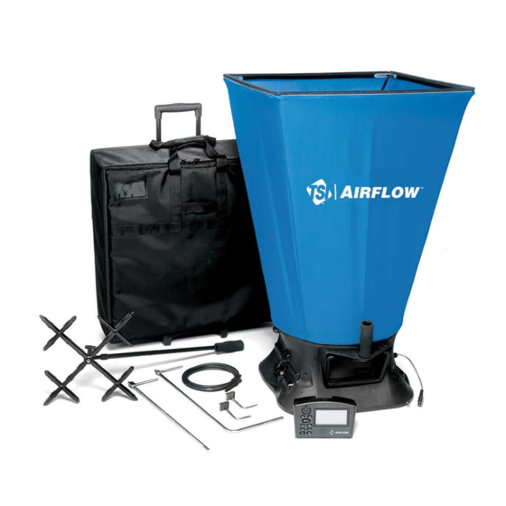
- Page 1 AIRFLOW™ INSTRUMENTS PROHOOD™ CAPTURE HOOD MODELS PH730/PH731 OWNER’S MANUAL P/N 6005724, REVISION D OCTOBER 2014 Model PH731 ProHood™ Model PH730 Micromanometer Capture Hood (shown with standard and optional accessories)
- Page 3 LIMITATION OF WARRANTY AND LIABILITY Copyright© TSI Incorporated / 2012-2014 / All rights reserved. LIMITATION OF WARRANTY AND LIABILITY (effective April 2014) (For country-specific terms and conditions outside of the USA, please visit www.tsi.com.) Seller warrants the goods sold hereunder, excluding software, under normal use and service as described in the operator's manual, to be free from defects in workmanship and material for twenty-four (24) months, or if less, the length of time specified in the operator's manual, from the date of shipment to the customer.
- Page 4 Service Policy Knowing that inoperative or defective instruments are as detrimental to TSI as they are to our customers, our service policy is designed to give prompt attention to any problems. If any malfunction is discovered, please contact your nearest sales office or representative, or call Customer Service department at (800) 874-2811 (USA) or (1) 651-490-2811 (International).
-
Page 5: Table Of Contents
CONTENTS About This Manual ............................v Formatting and Typography ........................v Technical Assistance—Help! ........................v Chapter 1. Introduction ..........................1 Instrument Description ..........................2 Micromanometer ..........................2 Micromanometer ............................. 4 Standard Tools ............................4 Pitot Tube ............................4 Static Pressure Probe ........................4 ProHood Capture Hoods ........................ - Page 6 Where to Take the Measurement ......................63 Traversing a Round Duct........................64 Traversing a Square Duct........................65 Appendix C. Swirl X Flow Conditioner for Airflow Instruments Model PH731 ProHood Capture Hood ..........................67 Description ............................67 Performance Data ..........................68...
-
Page 7: About This Manual
About This Manual This manual explains how to set up, operate and maintain the Airflow Instruments PH730/PH731. Please read it thoroughly before using the instrument. Formatting and Typography Step-by-step instructions are numbered in boldface type: 1, 2, 3, etc., set flush-left against the margin. - Page 8 (This page intentionally left blank)
-
Page 9: Chapter 1. Introduction
Chapter 1. Introduction The PH730/PH731 are lightweight and easy-to-use instruments packaged with a variety of accessories for measuring pressure, temperature, humidity, air velocity, and air volume. Features of the micromanometer include: Single-function keys for ease of use Auto-zero for pressure measurements, auto-density correction, and back-pressure compensation when used with a capture hood ... -
Page 10: Instrument Description
Instrument Description The basic PH730 includes a micromanometer, carrying case, 18 in. (46 cm) pitot tube, (2) static pressure ® ® probes, (2) 8 ft (2.4 m) Norprene tubing, user manual, LogDat-CH™ for Windows data downloading software and RS232 interface cable, neck strap, internal NiMH battery charger, (4) AA NiMH batteries, AC adapter, and NIST traceable certificate. - Page 11 Differential Pressure Ports Battery Compartment Figure 2: Features of the PH730/PH731 Micromanometer, Back View Figures 3 and 4 show the features of the ProHood Capture Hood. Removable Center Handle Backpressure Flap Actuator Switch to pause a reading or to Base Handle initiate backpressure compensation...
-
Page 12: Micromanometer
Backpressure Flap Flow Manifold Mount for Hood Temperature Support Pole (4) Sensor Figure 4: Features of the ProHood Capture Hood Base, Inside View Micromanometer The micromanometer is a multifunction instrument used to measure air velocity, air flow, absolute and differential pressure, temperature, and humidity measurements when used with the tools listed below. The lightweight micromanometer incorporates auto-zeroing for high-accuracy, low pressure measurements. -
Page 13: Optional Tools
Optional Tools This section gives a brief description of optional tools for the micromanometer. Velocity Matrix The velocity matrix is used to obtain area-averaged multi-point air velocity measurements useful in laboratory hood face velocity testing, filter face velocity testing, and other applications such as kitchen exhaust. - Page 14 (This page intentionally left blank) Airflow™ Instruments ProHood Capture Hoods PH730/PH731...
-
Page 15: Chapter 2. Unpacking And Setting Up
Tables 1 and 2 list available standard and optional components. Table 1: List of Standard and Optional Components Item Part No. Models PH730 and PH731 Electronic Balancing Tools (Airflow Instruments) PH730 PH731 Carrying case, PH730 1319378... -
Page 16: Preparing The Instrument For Use
Table 2: List of Optional Hood and Frame Kits Item Part No. 1 ft 4 ft (305 mm 1220 mm) fabric hood and frame kit 801200 2 ft 4 ft (610 mm 1220 mm) fabric hood and frame kit 801201 1 ft ... - Page 17 To select the type of batteries you are using: 1. Turn the unit off and locate the battery cover on the back of the micromanometer (see Figure 5). Figure 5: Battery Cover Removal 2. Press down on the compartment cover and slide it down. (The cover slides off.) 3.
-
Page 18: Using The Pressure Ports
To install replacement batteries: 1. Turn the unit off and locate the battery cover on the back of the micromanometer (see Figure 5). 2. Press down on the compartment cover and slide it down. (The cover slides off.) 3. Remove the battery holder by pulling up on the bottom (to loosen it) and then remove the battery holder. -
Page 19: Connecting A Pitot Tube
Connecting a Pitot Tube When the micromanometer is connected to a pitot tube, air velocity or air volume measurements can be taken. The pitot tube is connected to the (+) and (–) pressure ports on the micromanometer using two pieces of tubing of equal length. The total pressure port of the probe connects to the (+) port on the meter, and the static pressure port of the probe connects to the (–) port on the meter. -
Page 20: Attaching The Micromanometer To The Capture Hood Base
Attaching the Micromanometer to the Capture Hood Base 1. Tilt the meter forward and align the tabs in the base of the meter with the two matching slots in the bottom of the recessed area at the front of the base (see Figure 10). 2. -
Page 21: Connecting The Velocity Matrix To The Micromanometer
Connecting the Velocity Matrix to the Micromanometer The positive port (+) is located on the side of the Velocity Matrix that is opposite the handle assembly. The positive port (+) on the Velocity Matrix will be connected to the (+) port on the micromanometer, and the negative port (–) on the Velocity Matrix is connected to the (–) port on the micromanometer. -
Page 22: Connecting The Air Flow Probe To The Micromanometer
Connecting the Air Flow Probe to the Micromanometer When the micromanometer is connected to the Air Flow probe (straight pitot probe), air velocity or air volume measurements can be taken. The Air Flow probe is connected to the (+) and (–) pressure ports on the micromanometer using two pieces of tubing of equal length. -
Page 23: Connecting The Base Temperature Probe, Temperature And Humidity Probe Or Thermoanemometer Probe To The Micromanometer
Connecting the Base Temperature Probe, Temperature and Humidity Probe or Thermoanemometer Probe to the Micromanometer These probes have a “D” shape overmolding on the mini-DIN connector which must align with the connector on the right hand side of the micromanometer (see Figure 13). This will ensure the probe is properly connected and remains so during use. -
Page 24: Retracting The Probe
Retracting the Probe To retract the probe, hold the handle in one hand while gently pulling the probe cable until the smallest antenna section is retracted. C A U T I O N Do not use the instrument or probes near hazardous voltage sources since serious injury could result. -
Page 25: Chapter 3. Getting Started
Chapter 3. Getting Started This section provides information to help you quickly become familiar with the Micromanometer functions. Keypad Functions The keypad lets you enter information, initiate functions, and change values stored in the micromanometer. It will be helpful before operating the micromanometer to understand what each of the keys functions do. -
Page 26: Common Terms
Keypad Function Description Press to accept a menu selection, value or condition. Press to Start or Stop Enter ( ) Key data logging when in Continuous Key mode. READ Key If the Data Logging is set to Manual/Single, pressing the READ key begins a reading, which stops automatically when the reading is done. - Page 27 Term Description The logging interval is the period over which the instrument will average the Log Interval logged sample. For example, if the logging interval is set to 30 minutes, each sample will be the average over the previous 30 minutes. Log Interval is used with Cont-Key/RunAvg and Cont-time/RunAvg logging modes.
- Page 28 (This page intentionally left blank) Airflow™ Instruments ProHood Capture Hoods PH730/PH731...
-
Page 29: Chapter 4. Menu Setup And Navigation
Chapter 4. Menu Setup and Navigation Menus The menu structure is organized to allow easy MENU navigation and instrument setup utilizing the Pressure Tool arrow and keys. To exit a menu or menu Display Setup Flow Setup item, press the ESC key. Actual/Std Setup ... - Page 30 Table 3 identifies each Pressure Tool and the units of measure available each. Table 3: Pressure Tool Selection and Display Display Shows Tool Units Available Capture Hood l/s, m /hr, m /s, CFM with flow units Pressure units only Pressure Only in H O, mm H O, cm H...
-
Page 31: Display Setup
Display Setup Display Setup menu is where you will setup the desired parameters to be displayed on the instrument screen. With a parameter highlighted you can then use the ON arrow key to have it show up on the instrument screen or select the OFF arrow key to turn off the parameter. Use PRIMARY arrow key to have a parameter show up on the instrument screen in a larger display. -
Page 32: Flow Setup [Pitot Tube, Af Probe (Straight Pitot Tube) Or Thermoanemometer Probe]
Flow Setup [Pitot Tube, AF Probe (straight pitot tube) or Thermoanemometer Probe] In Flow Setup mode, there are three types when using a Pitot tube, AF probe or thermoanemometer probe: Round Duct, Rectangle Duct and Duct Area. Use the and keys to scroll through the types and then press the key to accept. -
Page 33: Actual/Standard Setup
Note Press/Kfact allows for calculating flow rate from diffusers or flow stations with pressure taps using the instruments pressure ports and Kfactors. The Kfactors are obtained from the diffuser or flow station manufacturer. For more information, refer to Application Note AF-114. -
Page 34: Settings
Settings Settings menu is where you can set the general SETTINGS settings. These include Language, Beeper, Select Language English Beeper Disable Units, Time Constant, Contrast, Set Time, Set Select Units Date, Time Format, Date Format, Number Format, Time Constant 1 Second Backlight, Auto Off. -
Page 35: Data Logging
Data Logging Measurements Measurements to be logged to memory are independent of measurements on the display, and must therefore be selected under DATA LOGGING Measurements. When set to ON, measurement will be logged to memory. When set to DISPLAY, measurement will be logged to memory if it is visible on the main running screen. - Page 36 MENU Pressure Tool Display Setup Flow Setup Actual/Std Setup Settings Data Logging DATA LOGGING Bluetooth Functions Measurements Applications LOG MODE/DISPLAY MODE Log Mode/Display Mode Manual/RunAvg Cf Selection Log Settings Calibration Manual/Single Choose Test Test 001 Name Test Manual/RunAvg Auto-Save/RunAvg View Data Cont-Key/RunAvg Delete Data Cont-Time/RunAvg...
- Page 37 Auto-Save/RunAvg Logging In Auto-Save/RunAvg mode, the user samples are automatically logged to memory at the end of the sampling period. To start logging, press the key. The Auto-Save/RunAvg mode is recommended when using the optional thermoanemometer probes. MENU Pressure Tool Display Setup Flow Setup Actual/Std Setup...
- Page 38 Cont-key Logging In Cont-key mode, the user starts logging by pressing SAVE or . The instrument will continue logging until , SAVE or ESC is pressed is pressed again. This mode would be used for long term data logging. MENU Pressure Tool Display Setup Flow Setup...
- Page 39 Cont-Time/RunAvg Logging In Cont-Time/RunAvg mode, the user starts taking readings by pressing SAVE or . The instrument will continue taking samples until the time as set in “Test Length” has elapsed or ESC, SAVE or is pressed. MENU Pressure Tool Display Setup Flow Setup Actual/Std Setup...
- Page 40 Choose Test Test IDs consist of a group of Samples that are used to determine statistics (average, minimum, and maximum) of a measurement application. The instrument can store 26,500+ samples and 100 test IDs (one sample can contain multiple measurement parameters such as flow and temperature). Example: Each duct traverse will have its own Test ID consisting of several Samples.
- Page 41 View Data/Choose Test To view stored data, first select the Test ID that contains the data to be recalled. This is accomplished in the Choose Test menu. MENU Pressure Tool Display Setup DATA LOGGING Flow Setup Measurements Actual/Std Setup Log Mode/Display Mode Manual/RunAvg Settings Log Settings...
- Page 42 View Samples MENU Pressure Tool Display Setup DATA LOGGING Flow Setup Measurements Actual/Std Setup Log Mode/Display Mode Manual/RunAvg Settings Log Settings Data Logging Choose Test Test 001 Bluetooth Functions VIEW DATA Name Test Applications Choose Test Test 022 View Data Cf Selection View Stats Delete Data...
- Page 43 Delete Data Use this menu item to delete all data, delete test or delete a sample. MENU Pressure Tool Display Setup DATA LOGGING Flow Setup Measurements Actual/Std Setup Log Mode/Display Mode Manual/RunAvg Settings Log Settings Data Logging Choose Test Test 022 Bluetooth Functions Name Test Applications...
- Page 44 Delete Test will clear stored data in an individual Test ID selected by the user. MENU Pressure Tool Display Setup DATA LOGGING Flow Setup Measurements Actual/Std Setup Log Mode/Display Mode Manual/RunAvg Settings Log Settings Data Logging Choose Test Test 005 Bluetooth Functions Name Test Applications...
-
Page 45: Bluetooth Functions
% Memory This option displays the memory available. Delete All, under Delete Data, will clear memory and reset the memory available to 100%. DATA LOGGING Measurements Log Mode/Display Mode Manual/RunAvg Log Settings Choose Test Test 001 Name Test View Data Delete Data % Memory MEMORY... -
Page 46: Applications
PINcode The PINcode is a security key to be entered into the computer if prompted. The factory default PINcode is 0000. Note PINcode must be set to 0000 in order to use 8934 printer. # AutoConnects Specifies how many times the instrument will attempt to reattach to a paired device after the power is turned on. - Page 47 Log Tcheb Duct Traverse The Log Tchebycheff duct traverse is a method of determining the average air velocity or air volume within round or rectangular ductwork. This application will show the round or rectangular duct on the display along with the number of sample points with insertion depth (inches or millimeters). For more information on this application and where to take the samples, refer to Appendix B of this manual.
-
Page 48: Calibration Factor (Cf) Selection
Calibration Factor (Cf) Selection The correction factor is an offset that can be applied to the velocity measurements when using the AF Probe, Pitot tube and Velocity Matrix or flow when using the Capture Hood. An offset of ±50% (0.50 to 1.50) can be applied to the measurement. Depending on what is selected as the Pressure Tool will determine what measurement tool is displayed on the Cf Selection screen. -
Page 49: Printing Data Using The Portable Printer
Printing Data Using the Portable Printer To print logged data, first enter the DATALOGGING menu. Then, use the CHOOSE TEST item to select the data to be printed. After the test is selected, use the VIEW STATS and VIEW SAMPLES items to select statistics or individual data points to view and print. - Page 50 (This page intentionally left blank) Airflow™ Instruments ProHood Capture Hoods PH730/PH731...
-
Page 51: Chapter 5. Changing Capture Hoods
Chapter 5. Changing Capture Hoods This chapter identifies the flow hood parts and gives instructions for assembling the flow hood. Capture Hood Parts Identification Figure 15 identifies the major parts of the capture hood, which are described in the following paragraphs. Before using the hood, please familiarize yourself with the various parts. - Page 52 Figure 16: Installing a Support Pole 4. Insert the second support pole into the pole mount on the opposite side of the base. 5. Repeat step 3 for the second support pole. 6. Repeat steps 4 and 5 for the remaining two support poles. Four other hood sizes are available from TSI and can be purchased separately.
-
Page 53: Alternate Hood Installation
Alternate Hood Installation Refer to Figures 17 through 20 to determine the frame channels needed to assemble any of the standard sized frames. Select the pieces required for the frame size desired and assemble with the aid of the appropriate figure. Each channel is labeled with its number for easy identification. Several sections (numbers 1, 3, and 4) consist of a straight channel portion (each a different length) and a corner piece. - Page 54 Figure 18: 2 ft 4 ft (610 mm 1220 mm) hood and frame. The support poles always cross as pairs at the front and back of the fabric hood. For the 2 ft 4 ft (610 mm 1220 mm), the support poles are inserted into the inside ferrule locations.
- Page 55 Figure 19: 1 ft 5 ft (305 mm 1525 mm) hood and frame. The support poles always cross as pairs at the front and back of the fabric hood. For the 1 ft 5 ft (305 mm 1525 mm), the support poles are inserted into the inside ferrule locations.
- Page 56 Figure 20: 3 ft 3 ft (915 mm 915 mm) hood and frame. The support poles always cross as pairs at the front and back of the fabric hood. For the 3 ft 3 ft (915 mm 915 mm), the support poles are inserted into the outside ferrule locations.
-
Page 57: Direct Inflow Measurement Hood For Biological Safety Cabinets
Figure 22: Frame Side Coupler Assembly Each hood is constructed in a trapezoidal shape, sewn together so that one open end forms a round attachment to the base, and the other forms a square or rectangle large enough to fit its matching frame assembly. - Page 58 The direct inflow BSC hood includes (see Figure 24): Fixed frame assembly with four removable flaps Fabric hood Hood support poles Base mounting hardware (threaded insert, washer, and screw) Telescopic pole stand with case to freely hold the capture hood in a vertical position when mounted to a biological safety cabinet or lab hood Figure 24: Direct Inflow Measurement Hood Components To complete the assembly of the BSC hood, follow these seven steps:...
- Page 59 3. Insert the flaps into the slots from the side of the frame where the fabric hood is attached to the U-channel of the frame (see Figure 26). Use the different flap lengths to fit various cabinet widths. Figure 26: Attach Fabric Hood and Hood Support Poles to Frame and Base Assembly 4.
- Page 60 5. Adjust the height and position of the telescopic stand so that the bottom part of the hood frame rests against the cabinet opening, and the capture hood is horizontal to the cabinet (see Figure 28). Figure 28: Adjust Height and Position of Telescopic Stand 6.
- Page 61 7. Adjust the flaps to cover the opening of the cabinet. Tape the edges of the flaps to the sash and frame of the cabinet to create a tight fit. The unit is now ready to make measurements (see Figure 30). Figure 30: Unit Ready to Make Measurements Chapter 5: Changing Capture Hoods...
- Page 62 (This page intentionally left blank) Airflow™ Instruments ProHood Capture Hoods PH730/PH731...
-
Page 63: Chapter 6. Flow Measurements Using The Capture Hood
Chapter 6. Flow Measurements Using the Capture Hood There are two methods of making flow measurement using Capture Hood: (1) Capture Hood (non-backpressure compensation). (2) Capture Hood with backpressure compensation. “Appendix A. Back Pressure,” for an explanation of the implications of capture hood-induced back (See pressure on the measured flow.) Supply or return flows can be measured with both methods, and return flow is indicated as a negative... -
Page 64: Running Average Measurements
Running Average Measurements In this mode, the instrument will measure continuously while displaying a running average of flow. Pressing either the READ key on the meter or the red switch on the base will hold the current reading. To restart the running average measurement, press the READ key or the red switch. The SAVE key can be used at any time to log to memory. -
Page 65: Error" Display
Note It is important that the capture hood see the same flow for both parts of the backpressure compensated flow measurement. It is best to keep the Capture Hood in place for both measurements, but it is alright to remove and replace the Capture Hood between the two readings. - Page 66 (This page intentionally left blank) Airflow™ Instruments ProHood Capture Hoods PH730/PH731...
-
Page 67: Chapter 7. Maintenance And Troubleshooting
If the fabric gets ripped it should be replaced or repaired. Duct tape can be placed over the rip on both sides of the fabric for temporary repair. To replace a damaged fabric or to order a different fabric size, contact your local TSI/Airflow Instruments products distributor. To determine who your local TSI/Airflow Instruments products distributor is, you may call toll-free at (800) 874-2811 (USA) or (1) 651-490-2811 (International). - Page 68 Table 4: Troubleshooting the Instrument Symptom Possible Causes Corrective Action No display Unit not turned on. Press I/O key. Low or dead batteries. Replace the batteries. Dirty battery contacts. Clean the battery contacts. AC adapter not connected. Plug in AC adapter. Low battery charge.
-
Page 69: Appendix A. Back Pressure
Appendix A. Back Pressure The quantity of air flowing through a supply diffuser or a return grille is reduced to some extent whenever a capture hood is placed over the flow opening. The amount of flow reduction will vary depending on the combined effects of the diffuser/grille resistance, the capture hood resistance, system pressure and the flow rate. - Page 70 (This page intentionally left blank) Airflow™ Instruments ProHood Capture Hoods PH730/PH731...
-
Page 71: Appendix B. Traversing A Duct To Determine Average Air Velocity Or Volume
Appendix B. Traversing a Duct to Determine Average Air Velocity or Volume The following techniques can be used to measure air flow inside ducts, using a velocity probe or pitot- static tube. When using a pitot-static tube, the individual velocities must be calculated for each pressure reading and then averaged together. -
Page 72: Traversing A Round Duct
Traversing a Round Duct Using the log-Tchebycheff method, the duct is divided into concentric circles, each containing equal area. An equal number of readings is taken from each circular area, thus obtaining the best average. Commonly, three concentric circles (6 measuring points per diameter) are used for ducts of 10-inch diameter and smaller. -
Page 73: Traversing A Square Duct
Traversing a Square Duct Using the log-Tchebycheff method, the duct is divided into rectangular areas, which are further adjusted in size to account for effects of the duct wall on the airflow. A minimum of 25 points must be measured in order to get a good average. - Page 74 (This page intentionally left blank) Airflow™ Instruments ProHood Capture Hoods PH730/PH731...
-
Page 75: Appendix C. Swirl X Flow Conditioner For Airflow Instruments Model Ph731 Prohood Capture Hood
Appendix C. Swirl X Flow Conditioner for Airflow Instruments Model PH731 ProHood Capture Hood Description The Swirl X Flow Conditioner significantly reduces the negative effects turbulent airflows have on the measurement accuracy of pressure-based capture hoods. The Swirl X Flow Conditioner creates a more uniform flow pattern within the hood and is ideally suited for Swirl or Twist-type supply air diffusers. -
Page 76: Performance Data
Performance Data Performance data obtained in HVAC test laboratory using two high-accuracy flow stations as flow measurement standards. The flow stations were mounted in sealed ductwork upstream of the tested Swirl Diffusers. PH731 Performance Data (Swirl Diffuser on 200mm Dia. Duct) PH731 with Swirl-X PH731 (No Swirl-X) PH731 Allowed Tolerance... -
Page 77: Installation And Usage
Installation and Usage 1. Put the two pieces together and place it in the base as shown below (it will sit on top of the flange of the base). 2. Install the support rods and 2’ x 2’ (610 mm x 610 mm) frame/fabric. 3. - Page 78 (This page intentionally left blank) Airflow™ Instruments ProHood Capture Hoods PH730/PH731...
- Page 79 Airflow Instruments Models PH730/PH731 Specifications Range Statistics ...... min, max, average Differential pressure ... ±15 in. H O (3735 pa); 150 in. Data Storage ....26,500 samples, time and date O maximum safe operating stamped pressure Logging Interval ..user selectable Absolute pressure ..
- Page 80 Airflow Instruments, TSI Instruments Ltd. Visit our website at www.airflowinstruments.co.uk for more information. Tel: +44 149 4 459200 Germany Tel: +49 241 523030 France Tel: +33 491 11 87 64 P/N 6005724 Rev D ©2014 TSI Incorporated Printed in U.S.A.
- Page 81 We represent this supplier. For more information contact Observator Instruments: T: +31 (0)180 463411 E: info@observator.com Rietdekkerstraat 6 2984 BM Ridderkerk The Netherlands Welcome to the world of Observator oriented company with a worldwide distribution network and offices Since 1924 Observator has evolved to be a trend-setting developer in Australia, Germany, the Netherlands, and supplier in a wide variety of industries.
Need help?
Do you have a question about the ProHood PH731 and is the answer not in the manual?
Questions and answers