Table of Contents
Advertisement
Quick Links
Advertisement
Table of Contents

Summary of Contents for Security Camera King VDB-EL2IRA-W
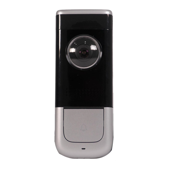
- Page 1 2MP Black Video Doorbell VDB-EL2IRA-W...
-
Page 2: Foreword
Foreword General This manual offers reference material and general information about the basic operation, maintenance, and troubleshooting for this Network Camera. Read, follow, and retain the following safety instructions. Heed all warning on the unit and in the operating instructions before operating the unit. - Page 3 About the Guide This user guide has been compiled with great care and the information it contains has been thoroughly reviewed and verified. The text was complete and correct at the time of printing. This guide may be periodically ...
- Page 4 Reorient or relocate the receiving antenna. Increase the separation between the equipment and receiver. Connect the equipment into an outlet on a circuit different from that to which the receiver is connected. Consult the dealer or an experienced radio/TV technician for help. ...
-
Page 5: Important Safeguards And Warnings
Important Safeguards and Warnings This chapter describes the contents covering proper handling of the device, hazard prevention, and prevention of property damage. Read these contents carefully before using the device, comply with them when using, and keep it well for future reference. Installation and Maintenance Professionals Requirements All installation and maintenance professionals must have adequate qualifications or ... - Page 6 An object has fallen on the unit. The unit has been dropped and the housing is damaged. The unit displays a marked change in performance. The unit does not operate in the expected manner when the user correctly follows the proper operating procedures.
- Page 7 Do not touch the CCD or the CMOS optic sensor. Use a blower to clean dust or dirt on the lens surface. Use a dry cloth dampened with alcohol and gently wipe away any dust on the lens. Use a dry soft cloth to clean the unit’s housing. If the unit is particularly dusty, use water to ...
-
Page 8: Cybersecurity Recommendations
Cybersecurity Recommendations Mandatory actions to be taken towards cybersecurity Change Passwords and Use Strong Passwords The number one reason systems get “hacked” is due to having weak or default passwords. It is recommended to change default passwords immediately and choose a strong password whenever possible. - Page 9 Change ONVIF Password Older IP camera firmware does not automatically change the ONVIF password when the system credentials are changed. Update the camera’s firmware to the latest revision or manually change the ONVIF password. Forward Only Ports You Need ...
- Page 10 Connect IP Cameras to the PoE Ports on the Back of an NVR Cameras connected to the PoE ports on the back of an NVR are isolated from the outside world and cannot be accessed directly. Isolate NVR and IP Camera Network ...
-
Page 11: Table Of Contents
Table of Contents Foreword ............................... I Important Safeguards and Warnings....................IV Cybersecurity Recommendations ....................VII Table of Contents ..........................X 1 Overview ............................1 Video Doorbell Components ..................... 1 LED Indicators .......................... 2 2 Installing the Camera ........................3 Installation Tips ......................... 3 Unpacking .......................... -
Page 12: Overview
Overview This doorbell offers Passive IR motion detection and transmits video and audio to a mobile phone for remote visual confirmation and communication with visitors. This device is compatible with NVRs and with the mobile application. The key features of this camera are: WiFi Capability This doorbell operates on the IEEE802.11b/g/n networks using the 2.4 GHz band. -
Page 13: Led Indicators
LED Indicators LED Indicator Light Device Status Spinning Blue Calling Solid Blue Talking Flashing Blue Network Error... -
Page 14: Installing The Camera
Installing the Camera The video doorbell ships with all the components to mount the camera to a wall. Before installing the camera consider the following: Review the “Installation Tips” section to help you choose an ideal mounting location. Decide whether to run the cables through the wall or along the wall. ... -
Page 15: Inserting An Sd Card
Inserting an SD Card Remove the M3x6 screw from the bottom of the unit, then remove the mounting bracket from the underside of the doorbell. Lift the SD card cover from the back of the doorbell. Gently push right to open the SD slot Door. Insert the SD card into the slot and gently push until it clicks into place Gently push left to close the SD Door. -
Page 16: Mounting The Doorbell To A Wall
Mounting the Doorbell to a Wall Figure 2-1: Doorbell Installation Schematic Remove the M3x6 screw from the bottom of the unit, then remove the mounting bracket from the underside of the doorbell. Use the mounting bracket as a template to mark the position of the three (3) screw holes and the hole for routing the wires. -
Page 17: Wiring The Doorbell To A Doorbell Chime
Wiring the Doorbell to a Doorbell Chime The Doorbell Video Doorbell connects directly to a mechanical or to an electric door chime with the aid of the included Doorbell Chime Kit. In general, the doorbell chime and the Doorbell are both connected to the AC power input and the transformer wire from the chime is connected to the Doorbell so that when a visitor pushes the DH-DB11 the chime plays the tone. -
Page 18: Wiring An Electrical Chime
2.6.2 Wiring an Electrical Chime Cut the power to the electrical door chime. Remove the back cover from the electrical chime to expose the electrical terminals. Disconnect the existing wires from the FRONT and the TRANS terminals. Connect the wire harness to the input port on the Chime Kit. Attach the end of the live wire to the TRANS terminal on the electric chime. - Page 19 Attach the other end of the TRANS wire to the AC power input. Attach the other end of the FRONT wire to a wire clip. Attach the live wire from the Doorbell to the AC power input Attach the other wire from the Doorbell to the wire clip connected to the FRONT wire from the electric chime.
-
Page 20: Troubleshooting
Troubleshooting Issue Solution Ensure you are using a 2.4GHz Wi-Fi network to configure the unit. The unit does not work with 5GHz Cannot boot device networks. Ensure the camera is properly connected to power Ensure your mobile device is within 1 ft (30 cm) of the ...
Need help?
Do you have a question about the VDB-EL2IRA-W and is the answer not in the manual?
Questions and answers