Advertisement
Quick Links
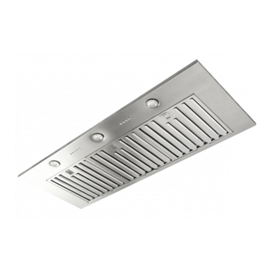
Model
08E W/P
Before beginning installation, please thoroughly read and become familiar with these instructions. Installation and
service must be completed by a qualified installer. Failure to properly install this product may void the warranty.
Installer:
Please leave Installation Instructions with the range hood liner.
Please keep Installation Instructions for local electrical inspector's use and for future reference.
Owner:
WARNINGS: Must be followed carefully to avoid personal injury.
IMPORTANT: Must be followed carefully to avoid damage or incorrect installation.
TIPS: Contain helpful information to facilitate installation.
WARNING! TO REDUCE THE RISK OF FIRE, ELECTRICAL SHOCK, OR INJURY TO
PERSONS OBSERVE THE FOLLOWING:
a) Use this unit only in the manner intended by the manufacturer. If you have any questions, please contact the
manufacturer at the address or telephone number listed in the warranty.
b) Before servicing or cleaning unit, switch power off at service panel and lock service panel and lock the service
disconnection means to prevent power from being switch on accidentally. When the service disconnecting means
cannot be locked, securely fasten a prominent warning device, such as a tag to the service panel.
CAUTION
-- For general ventilating use only. Do not use to exhaust hazardous or explosive materials
and vapors.
WARNING – TO REDUCE THE RISK OF A RANGE TOP GREASE FIRE:
a) Never leave surface units unattended at high settings. Boilovers cause smoking and greasy spillovers that may
ignite. Heat oils slowly on low or medium settings.
b) Always turn hood ON when cooking at high heat or when flambéing food (i.e. Crepes Suzette, Cherries Jubilee,
Peppercorn Beef Flambe').
c) Clean ventilating fans frequently. Grease should not be allowed to accumulate on fan or filter.
d) Use proper pan size. Always use cookware appropriate for the size of the surface element.
Installation Instructions, Revised 02/11/14
Front Panel
Dimensions
17-5/8" x 45"
READ AND SAVE THESE INSTRUCTIONS
INSTALLATION INSTRUCTIONS &
USE & CARE GUIDE
08E W/P Series Models
1
Advertisement

Summary of Contents for VMI Air-Pro 08E W/P
- Page 1 INSTALLATION INSTRUCTIONS & USE & CARE GUIDE 08E W/P Series Models Front Panel Model Dimensions 17-5/8” x 45” 08E W/P Before beginning installation, please thoroughly read and become familiar with these instructions. Installation and service must be completed by a qualified installer. Failure to properly install this product may void the warranty. Installer: Please leave Installation Instructions with the range hood liner.
- Page 2 WARNING! TO REDUCE THE RISK OF INJURY TO PERSONS IN THE EVENT OF A RANGE TOP GREASE FIRE, OBSERVE THE FOLLOWING: a) SMOTHER FLAMES with a close-fitting lid, cookie sheet, or metal tray, then turn off the burner. BE CAREFUL TO PREVENT BURNS.
- Page 3 PART 1 Preparation The following method is the standard installation. There may be some different cases depending on the structure where the mounting bracket is placed or the shape and mounting condition of the wood hood. In such a case, please arrange best possible way according to the condition of the place where the range hood is being installed.
- Page 4 PART 2 Range Hood Mounting Important Installation Note Removal of the front panel Before removing the stainless steel front panel on the unit, you must first remove the aluminum knob on the dimmer switch. This is accomplished by loosening the set screw located on the side of the knob, by means of an allen wrench (not supplied).
- Page 5 Fix the supplied hanging brackets on the body firmly. Insert the washer-head wood screws (M5.1×45) (not supplied) into the mounting wall to align with bracket keyhole (left and right). Allow about 5mm between the screwheads and wall for mounting the range hood. Hook the temporary fixing holes of the hanging bracket on the washer-head wood screws prepared in previous step, and tighten the screws.
- Page 6 ATTENTION INSTALLERS Mounting brackets for both the wall and island installations are included. Please refer to accessories for proper mounting bracket for your installation. Wall Mount uses the three L-Shaped hanging brackets. (Discard the large rectangular mounting bracket.) Island Mount uses the large rectangular mounting bracket. (Discard the three L-Shaped hanging brackets.) Mounting procedure for 08E P (Ceiling Mounting) Put 4 all thread rods (1/2”...
- Page 7 Using washers, spring washers, and double nuts, attach the range hood to all 4 threaded rods securely. Note: If taping from the outside is impossible, remove the exhaust pipe unit and insert the duct end to the range hood directly, then make inside taping on the duct end. Be sure to attach a roof/wall cap with damper in this case.
- Page 8 SPECIFICATION SHEET - 08E W/P 08E W/P VMI, Inc. Blower unit, Individual Specifications Dated January 8, 2014 Model: 08E W/P Stainless Steel Front Cover Panel Safety Standards: C-UL-US Listed Dimensions: Front Panel: 17 7/8" Deep x 45" Wide Housing Height: 9 1/2"...
- Page 9 PART 3 Planning the Installation The 08E W/P series ventilation modules are designed for installation inside wood hood canopies. Proper installation of the liner is directly related to the material from which the custom canopy is constructed. A qualified person must complete the installation of this unit. Plan the installation so that all minimum clearances are met or exceeded.
- Page 10 PART 4 Securing the Liner MOUNTING THE LINER Note: Some hoods will have 1/8” thick wood shims installed on all four sides of the inside of the hood and some hoods will not have shims. This is due to design variations. Insert the liner into the hood with the bottom of the liner flush with the bottom of the hood.
- Page 11 ENERGY SAVING TIPS: Eliminate air currents in the vicinity by shutting nearby windows and doors, turning off ceiling fans and adjusting the adjacent heating and air conditioning outlets if necessary. Place your largest pans on the rear burners whenever possible. Clean filters and grease laden surfaces often to improve efficiency. Always use lids on cookware to retain heat and moisture.
- Page 12 Factory Installed Variable-Speed Wiring Details Black 120 volt AC from electrical panel (usually black) White Neutral from electrical panel (white) Green Ground from electrical panel (usually green) Wiring Diagram 08E W/P Series Models House Electrical Panel Green White (N) 120V Black (L) Liner Installation Instructions, Revised 02/11/14...
- Page 13 (3) years from the date of purchase. VMI Inc., at its option, will repair or replace the complete unit or any defective component without charge providing that, if requested, the product or defective component is promptly returned, prepaid to the address below. This warranty may be voided if any unauthorized service, alterations or repairs are made to the product.
Need help?
Do you have a question about the Air-Pro 08E W/P and is the answer not in the manual?
Questions and answers