Table of Contents
Advertisement
Quick Links
Advertisement
Table of Contents

Related Manuals for Axesstel TX240G

Summary of Contents for Axesstel TX240G
- Page 1 1 ...
-
Page 2: Introduction
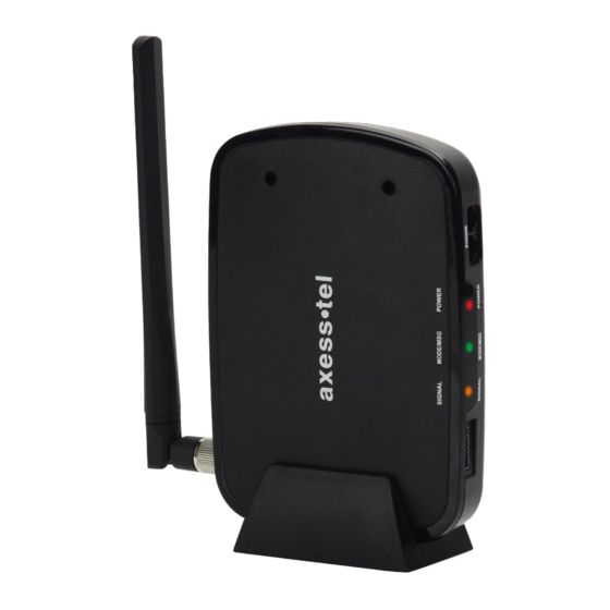
The Axesstel TX240G is a dual-band (800/1900Mhz) fixed wireless voice terminal that is perfect for a seamless land-line like service. TX240G is designed to provide a simple phone service at a home or business. Its Assisted GPS feature provides E911 service to accurately determine the location of the caller in case of an emergency. -
Page 3: Table Of Contents
TABLE OF CONTENTS INTRODUCTION........2 Using # as Send Key………….…………19 Overview...........2 Setting DTMF Length......19 Features............2 SECURITY Safety Precautions........4 Changing Lock Code…......20 Package Content………….......5 Restricting Outgoing Calls…....20 Factory Reset…….……….....21 BASIC INSTALLATION TTY/TDD Internal Battery Installation......6 Mode Setting…….……….....21 Setting Up the Terminal......6 Wall Jack Tester…….......7 OPTIONAL FEATURES RJ11 Cross Adaptor.........8 Call Waiting……………......23... -
Page 4: Safety Precautions
- The power cord is damaged. - The adapter has been damaged in any way. 7. Use only the AXESSTEL provided power adapter. Do not use the AXESSTEL power adapter for any other purposes. 8. Use only the AXESSTEL provided antenna. Do not use the antenna for any other purposes. -
Page 5: Package Content
After opening the package, check to make sure that you have all the parts shown below. If any item is missing or broken, please call your service provider’s support center. ① Axesstel 1x Fixed Wireless Terminal ② CDMA Dipole Antenna ③... -
Page 6: Basic Installation Internal Battery Installation
BASIC INSTALLATION INTERNAL BATTERY INSTALLATION This TX240G operates by receiving electricity from an electrical outlet or internal battery. 1. Open the battery cover on the bottom side of the terminal. 2. Connect the Battery power cable to the terminal. 3. Insert the battery pack in the right position between the hold bars. -
Page 7: Wall Jack Tester
Connecting the Terminal to Home Phone Wall Outlet. The TX240 can be connected to a home wall phone jack to generate a dial tone service throughout the entire home and allow users to use phones from any other home wall phone jack. Please verify that the home wall phone jacks do not have existing active telephone service and that they are not powered. - Page 8 RJ-11 CROSS ADAPTOR (Line 1 to Line 2 Bypass Adapter) If the first line of the phone line is live and has power, you may still be able to use the terminal through your home phone wiring by using the RJ-11 cross adapter. Line 1 uses the middle two pins on the RJ- 11 cable.
-
Page 9: A-Gps For E911
A-GPS for E911 Your terminal supports an A-GPS feature to meet a FCC 911 mandate, which makes the location of the terminal available to 911 operators in the case of emergency situations. During the emergency call, all the LEDs on the terminal will blink and your location can then be determined by the 911 operator. In order to increase the location accuracy, the external GPS antenna must be connected to the terminal and positioned at a location that can receive satellite signals, such as outside the home or building or near a window without obstructions to the sky. -
Page 10: Wall Mount Installation
WALL MOUNT INSTALLATION 1. Mark two mounting hole locations on a wall to match the screw holes on the back of the terminal. 2. Drill two holes and put screws at the marked locations. 3. Tighten the screws until the head is about 5mm from the wall. 4. -
Page 11: Led Indicators
GETTING TO KNOW THE TERMINAL LED INDICATORS Item Color Status Description POWER In Battery Mode: Fully Charged Full Solid In Adaptor Mode: Connected Green Blinking Charging Solid Mid Battery Level Orange Blinking Battery Error Solid Low Battery Blinking Low Battery Warning No Battery Solid Excellent Signal... -
Page 12: Audible Indicators
AUDIBLE INDICATIORS Tone Cadence Remark Continuous beep Terminal is in service area and Dial Tone 330ms ON / OFF can make calls. 660ms ON / OFF Beep - beep - beep Busy Tone Recipient line is busy 0.5s ON / 0.5s OFF High pitched beep Phone receiver is off the hook for Howler Tone... -
Page 13: Basic Operation
Basic Operation POWER ON/OFF MAKING CALLS RECEIVING CALLS ... - Page 14 POWER ON / OFF The power switch is located on the back side of the terminal 1. Turn on the unit by moving switch to ON position. 2. Turn off the unit by moving switch to OFF position. NOTE: When you turn on the terminal, it automatically searches for cellular service. After successfully acquiring cellular service, the Signal LED turns to Green, Orange or Red depending on signal strength.
-
Page 15: Receiving Calls
RECEIVING CALLS The wired or cordless telephone(s) connected to the terminal ring when an incoming call comes in. 1. Pick up the phone receiver to answer the call. 2. To disconnect after the call is finished, place the handset on the phone hook or press the TALK or OFF button on your phone. -
Page 16: Advanced Features
Advanced Features SOUND ○ ADJUSTING VOICE VOLUME ○ ADJUSTING ALERT TONE VOLUME ○ SETTING ONE MINUTE ALERT ○ SETTING VOICE PRIVACY ALERT ○ SETTING CONNECTION ALERT .GENERAL ○ SETTING CALLER ID ○ CALL WAITING ID ○ CALLER NAME DISPLAY ○ SETTING AUTO SEND TIME ○... - Page 17 SOUND ADJUSTING VOICE VOLUME You can control the volume level of the terminal. 1. Pick up the handset and listen to the dial-tone. □ □ □ □ □ 2. Press * to raise the voice volume. □ □ □ □ □...
- Page 18 SETTING CONNECTION ALERT If enabled, a discrete tone is generated on the receiver when a call is connected. To change the setting: 1. Pick up the handset. □ □ □ □ □ 2. Press # to enable the feature. □ □...
- Page 19 SETTING AUTOSEND TIME Similar to a landline phone, the terminal automatically makes the call shortly after the user finishes entering the phone number. To change the setting: 1. Pick up the handset. □ □ □ □ □ □ □ □ 2.
- Page 20 SECURITY CHANGING LOCK CODE The lock code prevents the terminal from being used by an unauthorized person without □ □ □ □ permission. The default lock code is To change the lock code: 1. Pick up the handset. □ □ □...
-
Page 21: Factory Reset
FACTORY RESET Reset the user configuration to factory default settings. 1. Pick up the handset. □ □ □ □ 2. Press 3. Enter the 4 digit lock code. If not correct, an error tone will sound and the terminal will return to standby mode. -
Page 22: Optional Features
Optional Features CALL WAITING THREE-WAY CALLING VOICE MAIL SERVICE 22 ... - Page 23 CALL WAITING Call Waiting is a feature which enables you to be alerted to a second incoming call when you are already on a phone call. Your service provider may or may not provide this feature. Please contact with your service provider to inquire. To use call waiting: 1.
-
Page 24: Miscellaneous
Miscellaneous MENU OPTION TABLE TROUBLESHOOTING SPECIFICATION ... - Page 25 MENU OPTION TABLE Access the menu by first lifting the handset or pressing the TALK button and their pressing ** followed by the appropriate number sequence as shown below. MENU Sub Menu ITEM EXAMPLE ("**○○") □ □ □ □ □ □...
-
Page 26: Troubleshooting
TROUBLESHOOTING Problem: I Can’t Place a Call 1. Check the Terminal’s Power LED to make sure the Terminal is ON. 2. Check the antenna to make sure it is tightly connected to the Terminal. 3. Check the phone cord to make sure it is properly connected between the Terminal’s RJ-11 port and the Telephone’s RJ-11 port. -
Page 27: Specification
- Weight: 268g Operating - Temperature: -10 ~ 50 ℃ ℃ Condition - Relative humidity : 10~95% AXT STD V 0.8 AXESSTEL INC. 6815 Flanders Drive Ste. 210 San Diego, CA 92121, USA www.axesstel.com © Axesstel Inc, All Rights Reserved ... - Page 28 28 ...
Need help?
Do you have a question about the TX240G and is the answer not in the manual?
Questions and answers