Table of Contents
Advertisement
Quick Links
Advertisement
Table of Contents

Related Manuals for Powermatic 1794860K

Summary of Contents for Powermatic 1794860K
- Page 1 Operating Instructions and Parts Manual Sliding Table for PM2000B and PM3000B Table Saws Powermatic 427 New Sanford Road LaVergne, Tennessee 37086 Part No. M-1794860 Ph.: 800-274-6848 Edition 2 06/2019 www.powermatic.com Copyright © 2018 Powermatic ...
-
Page 2: Important Safety Instructions
If used for other injury. purposes, Powermatic disclaims any real or 20. Maintain a balanced stance at all times so that implied warranty and holds itself harmless from you do not fall or lean against the blade or other any injury that may result from that use. -
Page 3: Kickback
1.1 Kickback 27. Do not attempt to saw boards with loose knots or with nails or other foreign material, on its The most common accidents among table saw surface. Do not attempt to saw twisted, warped users, according to statistics, can be linked to or bowed stock unless one edge has been kickback, the high-speed expulsion of material from jointed for guiding purposes prior to sawing. -
Page 4: About This Manual
If there are questions or comments, please contact your local supplier or Powermatic. Powermatic can also be reached at our web site: www.powermatic.com. -
Page 5: Table Of Contents
1.1 Kickback ..............................3 2.0 About this manual ............................4 3.0 Table of contents ............................5 4.0 Specifications for Powermatic Sliding Table ....................6 5.0 Features and terminology ..........................7 6.0 Unpacking ..............................8 ... -
Page 6: Specifications For Powermatic Sliding Table
L=length, W=width, H=height The specifications in this manual were current at time of publication, but because of our policy of continuous improvement, Powermatic reserves the right to change specifications at any time and without prior notice, without incurring obligations. ... -
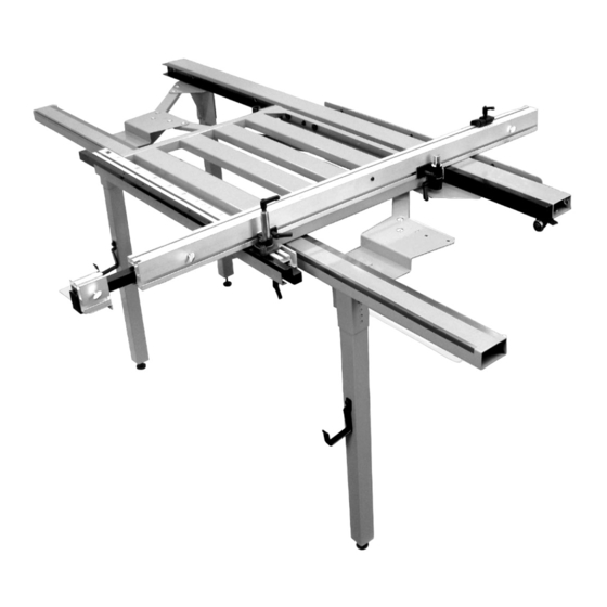
Page 7: Features And Terminology
5.0 Features and terminology These major components of the Sliding Table are referenced throughout the manual. Figure 5-1: features and terminology 7 ... -
Page 8: Unpacking
Hardware bag 1: Read and understand the entire Storage hooks – HB10 contents of this manual before attempting set- 11 Flat washers 8mm – HB11 up or operation. Hex cap screws M8x16 – HB12 Hex nuts M8 – HB13 Levelers –... - Page 9 Figure 6-1: Box #1 contents (p/n 1794860R) Figure 6-2: Box #2 contents (p/n 1794860T) Not to scale 9 ...
-
Page 10: Setup And Assembly
Cardboard or wood shims, approx. 1/8-inch thick * A ratchet wrench with sockets will speed assembly time. 7.2 Preparation Position your Powermatic table saw in its final location, with sufficient space on all sides for operation, loading and off-loading of stock, and Figure 7-1 maintenance. -
Page 11: Rail Assembly
7.4 Rail assembly Position inner guide rail (A) as shown in Figure 7-5, and mount right leg bracket assembly to Use HARDWARE BAG 2 the threaded holes in rail, in the orientation shown. Finger tighten screws only. Install mounting bracket (E, Figure 7-3) to saw table, as shown. -
Page 12: Linkages And Outer Rail
7.5 Linkages and outer rail Use HARDWARE BAG 3 Install two short linkages (J) and one long linkage (F) with carriage bolts, washers and cap nuts. See Figure 7-7. Finger tighten only. Figure 7-9 7.6 Table installation Use HARDWARE BAG 4 Figure 7-7 Set table (M, figure 7-10) onto rails. - Page 13 7.6.1 Table alignments For cutting accuracy, the table must slide smoothly and evenly without binding or “play.” Lateral and vertical play can be eliminated as follows. To correct lateral play, loosen bearing screw , Figure 7-12), and turn eccentric nut (M Figure 7-13) until bearing slightly contacts outer rail.
-
Page 14: Angle Adjusting Rail Installation
Vertical play at the outer rail has now been 15. Slide table forward and back the full extent of its corrected. To eliminate vertical play at the inner rail: travel. It should slide smoothly without bumps or thumping noises as it engages the rails. 11. -
Page 15: Fence Installation
Figure 7-22 Figure 7-24 7.8 Fence installation Flip fence upright (scale faces upward), and install fence into pivot hub on the right. See Use HARDWARE BAG 4 Figure 7-25. Install two locking handles (HB40, Figure 7-23) Slide angle clamp along fence until T-nut can be into the pivot hubs on table. -
Page 16: Flip Stop
(not tooth edges). 7.10 Assembly completion With fence mounted in front position, loosen On your Powermatic table saw, mount on/off switch screw (D , Figure 8-2) and slide fence scale (D to guide tube, and reinstall motor cover. -
Page 17: Fence-To-Blade Squareness
If variation occurs, loosen screws beneath outer Loosen screw (C , Figure 8-6) on angle rail and rail (see Figure 7-15) and shift front or back end slide angle scale (C ) until zero is aligned with of outer rail, as needed. Slide table forward and vertical face of fence. -
Page 18: Fence Scale And Flip Stop
8.4 Fence scale and flip stop 8.4.1 Fence at front position Loosen screw (D Figure 8-11) and move fence scale (D ) flush with right end of fence. Tighten screw (D Figure 8-8 Flip fence right side up, rotate 180-degrees, and install it in rear position: Place pivot post into hub, and slide angle clamp into channel of miter fence. -
Page 19: Capacity Adjustment
Figure 9-1 (Blade guard removed for clarity only, install guard before operating saw.) Figure 8-13 With fence in rear position, cutting capacity is 41- 8.4.1 Fence at rear position inches with panel clearing blade; 49-inches without With fence at rear position, loosen screw (D Figure panel clearing blade. -
Page 20: User-Maintenance
For large panels with fence in rear position, found at local hardware stores, or may be ordered loosen handle (S, Figure 9-3) and pull out fence from Powermatic. extension bar. Tighten bar in position, and use it to help push panel through the cut. - Page 21 11.1.1 Table Assembly – Exploded View 2 1...
- Page 22 11.1.2 Table Assembly – Parts List Index No Part No Description Size ....1794860T ....Table Assembly (includes #1 thru #83) ............1 ....PMST48-101 ..... T-Nut ......................6 2 ....PMST48-102 ..... Lock Lever ..................... 4 3 ....
- Page 23 Index No Part No Description Size 59 ....TS-1550021 ....Flat Washer ............. 4.3 x 10 x 1T ....2 60 ....TS-1532042 ....Phillips Pan Head Machine Screw ......M4-0.7P x 12L ....2 61 ....PMST48-161 ..... Left Leg Bracket .................... 2 62 ....
-
Page 24: Rail Assembly - Exploded View
11.2.1 Rail Assembly – Exploded View 2 4... -
Page 25: Rail Assembly - Parts List
11.2.2 Rail Assembly – Parts List Index No Part No Description Size ....1794860R ....Rail Assembly (includes #1 thru #20) ............1 1 ....PMST48-201 ..... Plastic Plug ....................1 2 ....PMST48-202 ..... Table Push Bar ....................1 3 .... -
Page 26: Warranty And Service
Powermatic sells through distributors only. The specifications listed in Powermatic printed materials and on the official Powermatic website are given as general information and are not binding. Powermatic reserves the right to effect at any time, without prior notice, those alterations to parts, fittings, and accessory equipment which they may deem necessary for any reason whatsoever. - Page 27 This page intentionally left blank. 2 7...
- Page 28 427 New Sanford Road LaVergne, Tennessee 37086 Phone: 800-274-6848 www.powermatic.com 2 8...
Need help?
Do you have a question about the 1794860K and is the answer not in the manual?
Questions and answers