Table of Contents
Advertisement
Quick Links
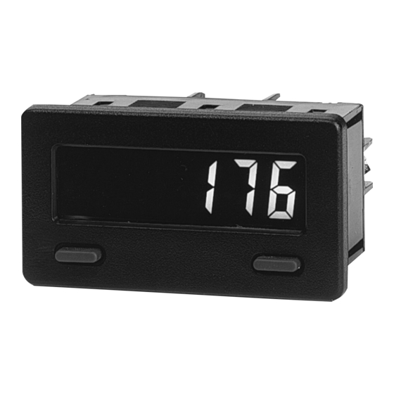
MODEL CUB5 - MINIATURE ELECTRONIC 8-DIGIT DUAL
GENERAL DESCRIPTION
The CUB5 provides the user the ultimate in flexibility, from it's complete
user programming to the optional relay output capability. The meter can be
programmed as a single or dual counter with rate indication capability. The
display can be toggled either manually or automatically between the
selected displays.
The CUB5 display has 0.46" (11.7 mm) high digits. The LCD is available in
two versions, reflective (CUB5R000) and backlight (CUB5B000). The
backlight version is user selectable for green or red backlighting with variable
display intensity.
The counter is programmable for one of eight different count modes,
including bi-directional and quadrature. When programmed as a dual counter,
each counter has a separate scale factor and decimal points. In the counter/rate
indicator mode, each have their own scaling and decimal point read-outs in
different engineering units.
The meter has two separate inputs which provide different functions
depending on which operating mode is selected. Input A accepts the signal for
the Count and or Rate displays, while Input B accepts the signal for the Count
display or direction control. In the anti-coincidence mode, both inputs are
monitored simultaneously so that no counts are lost. The resulting display can
be chosen as the sum or difference of the two inputs. The Rate Indicator has
programmable low (minimum) and high (maximum) update times to provide
optimal display response at any input frequency. There is a programmable user
input that can be programmed to perform a variety of functions.
The capability of the CUB5 can be easily expanded with the addition of an
option module. Setpoint capability is field installable with the addition of the
CUB5RLY0, relay output module.
The CUB5 can be powered from an optional Red Lion Micro-Line/Sensor
Power Supply (MLPS1000), which attaches directly to the back of a CUB5. The
MLPS1 is powered from 85 to 250 VAC and provides up to 400 mA to drive the
unit and sensors.
DIMENSIONS In inches (mm)
SILGE ELECTRONICA S.A.
Av. Mitre 950 – B1604AKN - Florida Tel. 4730-1001-Fax: 4760-4950
ventas@silge.com.ar
Email:
COUNTER AND RATE INDICATOR
Note: Recommended minimum clearance (behind the panel) for mounting clip installation is 2.15" (54.6) H x 3.00" (76.2) W.
Internet: http://www.silge.com.ar
LCD, REFLECTIVE OR GREEN/RED LED BACKLIGHTING
G
0.46" (11.7 mm) HIGH DIGITS
G
OPTIONAL RELAY OUTPUT MODULE
G
COUNT SPEEDS UP TO 20 KHZ (HIGH SPEED INPUT)
G
OPERATES FROM 9 TO 28 VDC POWER SOURCE
G
PROGRAMMABLE SCALING FOR COUNT AND RATE
G
BI-DIRECTIONAL COUNTING, UP/DOWN CONTROL
G
QUADRATURE SENSING (UP TO 4 TIMES RESOLUTION)
G
ANTI-COINCIDENCE COUNTING (ADD/ADD & ADD/SUB)
G
NEMA 4X/IP65 SEALED FRONT BEZEL
G
COUNTER
The CUB5 receives incoming pulses and multiplies them by the Count Scale
Factor. The unit's counter (internal count value) keeps track of the scaled input
pulse count which results in the desired reading value for the count display. Input
A accepts the signal for the count and Input B is used for quadrature, dual counter,
anti-coincidence counting, or up/down control counting.
RATE
The rate indicator utilizes the signal at Input A to calculate the rate value using
a time interval method (1/tau). The unit counts on the negative edge of the input
pulses. After the programmed minimum update time elapses and the next negative
edge occurs, the unit counts the number or edges that occurred during the elapsed
time. The number of edges is multiplied by the rate scaling value to calculate the
rate value. At slower rates, averaging can be accomplished by programming the
rate minimum update time for the desired response. Extensive scaling capabilities
allow practically any desired reading at very slow count rates.
SAFETY SUMMARY
All safety related regulations, local codes and instructions that appear in this
literature or on equipment must be observed to ensure personal safety and to
prevent damage to either the instrument or equipment connected to it. If
equipment is used in a manner not specified by the manufacturer, the protection
provided by the equipment may be impaired.
Do not use this meter to directly command motors, valves, or other actuators
not equipped with safeguards. To do so can be potentially harmful to persons or
equipment in the event of a fault to the meter.
CAUTION: Read complete
instructions prior to installation
and operation of the unit.
1
Bulletin No. CUB5-X
Drawing No. LP0584
Effective 8/04
CAUTION: Risk of electric shock.
Advertisement
Table of Contents

Summary of Contents for Silge Electronica Red lion CUB5
- Page 1 Bulletin No. CUB5-X Drawing No. LP0584 Effective 8/04 SILGE ELECTRONICA S.A. Av. Mitre 950 – B1604AKN - Florida Tel. 4730-1001-Fax: 4760-4950 ventas@silge.com.ar Email: Internet: http://www.silge.com.ar MODEL CUB5 - MINIATURE ELECTRONIC 8-DIGIT DUAL COUNTER AND RATE INDICATOR LCD, REFLECTIVE OR GREEN/RED LED BACKLIGHTING 0.46"...
-
Page 2: Meter Specifications
ABLE ONTENTS Ordering Information ......2 Installing Plug-In Card ......4 General Meter Specifications. -
Page 3: Dip Switches
PTIONAL UTPUT Adding Option Card WARNING: Disconnect all power to the unit before installing Plug-in card. The CUB5 meters can be fitted with an optional relay card. The details for the plug-in card can be reviewed in the specification section below. The plug-in card can be installed initially or at a later date. -
Page 4: Wiring The Meter
3.0 I NSTALLING The Plug-in card is separately purchased optional card that performs specific CAUTION: The Plug-in card and main circuit board contain static functions. The card plugs into the main circuit board of the meter. sensitive components. Before handling the cards, discharge static charges from your body by touching a grounded bare metal object. -
Page 5: Input Wiring
4.3 INPUT WIRING CAUTION: Power input common is NOT isolated from user input common. In order to preserve the safety of the meter application, the power input common must be suitably isolated from hazardous live earth referenced voltage; or input common must be at protective earth ground potential. If not, hazardous voltage may be present at the User Inputs and User Input Common terminals. -
Page 6: Programming Menu
5.0 R EVIEWING THE RONT UTTONS AND ISPLAY DISPLAY MODE OPERATION ENTERING PROGRAM MODE PROGRAMMING MODE OPERATION Index display through selected displays Press and hold for 2 seconds to activate Store selected parameter and index to next parameter Advances through the program menu/Increments Resets count display Press SEL to enter programming mode selected parameter value or selection... -
Page 7: Parameter Menu
6.1 MODULE 1 - I 1-INPUt NPUT ETUP ARAMETERS PARAMETER MENU Shaded area selections only apply when programmed for dual count mode. COUNT MODE COUNTER B SCALE FACTOR Cntb ScF Cnt ud qUAd 1 Add Add 00. 0 001 99. 9 999 INP A-b RAtE Cnt qUAd 2... - Page 8 USER INPUT FUNCTION PROGRAMMING MODE ACCESS USEr INP SECURITY USER INPUT USER INPUT PROGRAMMING MODE ACCESS CODE FUNCTION STATE Pro Loc ----- Immediate access After entering security code Pro Loc DISPLAY MODE DESCRIPTION >0 ----- Pro CodE prompt No Function User Input disabled.
- Page 9 SCALING FOR RATE INDICATION INPUT FREQUENCY CALCULATION To scale the Rate, enter a Scaling Display value with a corresponding Scaling The meter determines the input frequency by summing the number of falling Input value. These values are internally plotted to a Display value of 0 and Input edges received during a sample period of time.
- Page 10 6.3 MODULE 3 - D ISPLAY AND RONT ANEL 3-dSPLAY ARAMETERS PARAMETER MENU FRONT PANEL DISPLAY SELECT ENABLE (SEL) DISPLAY INTENSITY LEVEL (BACKLIGHT UNIT ONLY) SEL Enb d-LEVEL selection allows the button to toggle through the enabled Enter the desired Display Intensity Level (1-5). The display will actively dim or brighten as levels are changed.
- Page 11 SETPOINT OUTPUT ACTIONS COUNTER A RESET ACTION SPT ACTION DESCRIPTION OUTPUT ACTIVATES OUTPUT DEACTIVATES CmtA rSt When Count = At Manual Reset to ZErO to SPt LAtCH Latched Output Mode to ZErO SPt rSt Setpoint When Count = After Setpoint t-OUt Timed Output Mode Setpoint...
- Page 12 CUB5 PROGRAMMING QUICK OVERVIEW...
Need help?
Do you have a question about the Red lion CUB5 and is the answer not in the manual?
Questions and answers