Table of Contents
Advertisement
Quick Links
To use this analyzer with safety and effectiveness, please read this
manual before usage.
This manual applies to the product model NGA 6000.
1. This manual should be referred with regard to the product design and safety
assurance of the configuration.
2. For the purpose of safe confirmation, this manual should be provided to the
end user at the same time with the supply of the product.
3. Please use only in well-ventilated place.
4. This product should not be washed/polished by volatile or toxic
chemical materials like thinner.
5. Please don't use the printer until the printing paper is prepared.
6. If the equipment is wiped with a piece of moistened gauze, dry the equipment
thoroughly before use.
Using the monitor while it is wet may result in an electric shock.
7. Do not clean the terminals or the AC power inlet. Otherwise, deformation or
corrosion of contacts could occur,
which may result in contact failure and/or malfunction of the equipment.
- The contents of this manual may be changed without notice for the
purpose of functional improvement.
Notes for User
Copyright © NEXTECH CO., LTD.
Advertisement
Table of Contents

Summary of Contents for Carman NGA6000
-
Page 1: Notes For User
Notes for User To use this analyzer with safety and effectiveness, please read this manual before usage. This manual applies to the product model NGA 6000. 1. This manual should be referred with regard to the product design and safety assurance of the configuration. -
Page 2: Table Of Contents
Contents Notes for user ..………………….......…..…....1 Contents ......……............…..2 Chapter 1. Quality Guarantee Provision ............…....4 1-1 Guarantee provision ..........…....4 1-2 Guarantee claim procedure Chapter 2. Safety Instruction ............…....5 2-1 Usage purpose ............….....5 2-2 Usage condition .............…..…..5 2-3 Caution and warning Chapter 3. Introduction of NGA 6000 ..............…...6 3-1 Specification ..............……..7... - Page 3 ..............…..28 6-4. Zero calibration ..............……..30 6-5. Measurement ................…….…..31 6-6. Hold ................……..31 6-7. Print Chapter 7. Selection Mode ............…....33 7-1. Key functions ..............…..…..33 7-2. Leak test ..........……....36 7-3. Remaining HC test ............…....37 7-4. Selection of fuel .....…........….....39 7-5. HCV and OCV setup .......…........…....40 7-6.
-
Page 4: Chapter 1. Quality Guarantee Provision
Chapter 1. Quality Guarantee Provision 1-1 Guarantee provision If the product is handled according to this manual but there occurs a failure with in the guaranteed period, it will be repaired free of charge by our company. However, the compensation from the secondary damage and the following cases may not be guaranteed and repaired without fee: (1) A damage or fault, which occurs due to mishandling in use and negligence in maintenance and keeping. -
Page 5: Chapter 2. Safety Instruction
Chapter 2. Safety Instructions 2-1. Purpose of usage This analyzer is a equipment to measure the gas emission density of an automobile enabling to diagnose the automobile status and its preventive maintenance so that it can provide a function to prevent the air pollution in advance. 2-2. -
Page 6: Specification
Chapter 3. Introduction of NGA 6000 3-1 Specification NGA 6000 CO, HC, CO2, O2, Lambda(air surplus rate), Measuring item AFR, NOX (optional) Measuring CO, HC, CO2 : NDIR Method method O2, NOx : Electrochemical Cell Measuring range 0.00 ~ 9.99% 0 ~ 9999 ppm Resolution 0.01%... -
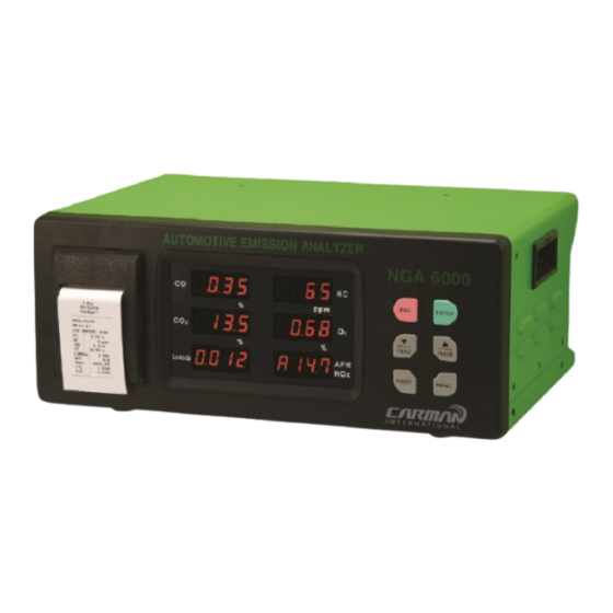
Page 7: Appearance
3-2 Appearance This manual is explaining mainly HOW TO USE 4GAS analyzer. 5GAS analyzer is just added with NO sensor on 4GAS analyzer. So, for 5GAS analyzer, use this same manual. You also can use the same manual for motorcycle which emits high density of HC. -
Page 8: Front View And Description
3-3. Front view and description 3-3-1 CO display window This displays the CO density and program proceeding status. 3-3-2 HC display window This displays the HC density and program proceeding status. 3-3-3 CO2 display window This displays the CO2 density and program proceeding status. 3-3-4 O2 display window This displays the O2 density and program proceeding status. - Page 9 3-3-7 PRINT Used in time of holding or printing. 3-3-8 MENU Used in choosing a supplementary function. ▼ 3-3-9 ZERO Used in time of correcting the datum point or moving a figure or digit. ▲ 3-3-10 PURGE Used in time of doing a purge or executing a value increase. 3-3-11 ENTER KEY Used in time of measuring or approving a supplementary function.
-
Page 10: Rear View And Description
3-4 Rear view and description 3-4-1 CAL(Calibration) This is a gas inflow gate used in time of standard gas adjustment. 3-4-2 INLET This is a measuring inlet where one end of the probe mounted into this inlet in time of gas emission measurement. - Page 11 3-4-7 GAS OUTLET This is a emitting outlet where the emitting gas and standard gas is outcome in the time of adding the NOx. 3-4-8 OPTION This is a terminal to be directly connected with a normal PC printer. 3-4-9 RS232 PORT This is a communication terminal through which a PC can operate the program.
-
Page 12: Basic Accessory
3-5 Basic accessory 3-5-1 Basic accessory... - Page 13 3-5-2 Basic accessory lists PART PART NAME Q'TY NUMBER PROBE QG0-M026 PROBE HOSE QG0-A015 LEAK TEST CAP QG0-A122 OPERATION MANUAL QG4-M071 1 COPY MAIN FILTER QG0-A017 10PC DUST FILTER QG0-A013 ZERO FILTER QG0-A014 PROBE FILTER QG0-A021 10PC FUSE (250V 2A) QG0-E022 POWER CABLE QG0-E019...
-
Page 14: Measuring Principal
Chapter 4. Circuits of NGA 6000 4-1 Measuring principal This analyzer is configured to perform a measurement by applying Non Dispersive Infra-Red (NDIR) method for analyzing CO, HC, and CO2, and electrochemical method for analyzing O2 and NOx. In the NDIR analyzing method, a flashing ramp which flashes the infrared rays is attached at the one end of the sample cell and at the other end a detecting sensor is attached so that it can detect the component of a gas and then calculate the gas density. -
Page 15: Guiding Diagram
4-2 Guiding diagram 4-3 Electrical circuit diagram... -
Page 16: Chapter 5. Installation Method And Notes
Chapter 5. Installation Methods and Notes 5-1 Installation 5-1-1 Fit end of the probe hose into the measuring probe and the other end of the hose into the gas inlet in the rear of the analyzer. If the fitting condition is not good and the air comes into flow from outside, it may yield an incorrect measured value. - Page 17 5-1-3 Verify the fitting conditions of measuring probe filter and various filters located in the rear of the analyzer. 5-1-4 Verify again the connection status of the analyzer and then turn on the power switch. 5-1-5 Connect the ground cable to GROUND on the rear of the analyzer.
-
Page 18: Notes
5-2 Notes ▶ This analyzer is operated with AC110V only or AC220V only. Please verify the power source before use. (Note that you can not change power source which is fixed upon supplying this analyzer.) ▶ The following factors should be considered to properly locate the analyzer body : ━... -
Page 19: Chapter 6. Measurement Mode
6. Measurement Mode 6-1. Warming- Up ① Switch the power [ON]. NGA 6000 will perform the initialization process for 10 seconds, displaying the following. Lambda ② NGA 6000 will display current set date and time for about five seconds. Lambda (E.g: May 15th, 2006, PM 1 : 25) - Page 20 ③ After displaying the current date and time, NGA 6000 will perform the self-diagnosis in the order of display window verification, communication, internal sensor, and memory as follows. If the items diagnosed are normal, NGA 6000 will display the [PASS] message. (Self-diagnosis execution screen) Lambda ↓...
- Page 21 Lambda ↓ Lambda ↓ Lambda...
- Page 22 ④ Upon completing the self-diagnosis, the screen displays as shown in the figure below. ⑤ The warming-up will be performed while the counter-value decreases by 1 between 120 and 480. ( Perform the warming-up for 2 through 8 minutes according to the neighboring temperature or the status of equipment use.
- Page 23 ⑦ Upon completion of the zero calibration, the following messages will be indicated on the window showing that NGA 6000 is in a ready for measurement. Lambda Power ON Initialization Process (10 seconds) Self Diagnosis Warming up (between 2 and 8 minutes) Zero Calibration (20 seconds)
-
Page 24: Stand-By
6-2. Stand-By The standby means when NGA 6000 is in a non-measurement state for a long period of time. In this state, the power is switched [ON] while the suction pump is switched [OFF]. ENTER ZERO PURGE PRINT MENU Press the key after the measurement or the purge function. - Page 25 NGA 6000 has the power-saving software in it. It operates in a measurement mode and then turns into a standby mode after 10 minutes as the pump automatically switches itself OFF. It is also programmed to operate in a purge mode for just 10 minutes and turns to be in a standby mode automatically.
-
Page 26: Purge
6-3. Purge The [PURGE] mode indicates that the gas remaining in the sample-cell in NGA 6000 is being cleared up with a clean air from the probe. PURGE mode of NGA 6000 cleans the probe for about 120 seconds and internal sample cell for 20 seconds. - Page 27 Lambda ③ When zero calibration is finished, it is automatically switched to standby mode. ★ Press the PURGE key one more time during the PURGE operation, and the PURGE function is performed for 30 minutes. After continuously using the exhaust gas of a vehicle for a long time, there may be lots of remaining gas in the probe and sample-cell.
-
Page 28: Zero Calibration
Note Build up a habit to clean NGA 6000 with the [PURGE] function for at least 10 minutes upon completion of the daily routine operation before switching the power off. It maintains the accuracy of NGA 6000 and prolongs the life cycle of the equipment. - Page 29 ② After the zero calibration followed by indicated messages, NGA 6000 is in a measurement ready state. Lambda Note 1 If the values are indicated as more than CO: 0.05%, HC: 30ppm even after the zero calibration, press the PURGE key again to clean the inside of NGA 6000 with a clean air for about 2~3 minutes.
-
Page 30: Measurement
6-5. Measurement ① Place the probe in the clean air to perform the [ Zero calibration ]. ② Push the probe deep into the exhaust outlet of the vehicle and measure exhaust gas by pressing measurement key. ENTER ZERO PURGE PRINT... -
Page 31: Hold
6-6. Hold ① This function stops measurement screen temporarily. ② This operates only in measuring state. ENTER ZERO PURGE PRINT MENU ③ If you press PRINT key once, measurement screen stops. * If you return to measurements state, press key. - Page 32 Lambda ④ Press the key, and the blinking figure increases. After adjusting the desired figure, press the ▲ key and the figure in the next digit blinks. After registering the car number by using the ▼ ▼ keys, press the PRINT key.
-
Page 33: Key Functions
7. Selection Mode 7-1. Key functions Contents Use the key to perform the leak test, the PEP value indication, the program version indication, and the standard gas calibration. Press the [MENU] key and NGA 6000 will operate as shown below. →... - Page 34 ① Press the MENU key once in the stand-by mode to select the Leak Test mode. Lambda ② If the message ‘Leak test’ is indicated on the indication window as shown above, mount the leak test cap on the front side of the probe. ③...
- Page 35 Lambda (When leak test is fine) Lambda (When leak is identified) ④ NGA 6000 returns to the Standby mode automatically unless other keys are pressed within 30 seconds after the leak test. When the result is indicated as FAIL ...
-
Page 36: Remaining Hc Test
7-3. Remaining HC test This test measures HC element accumulated in sample extract probe line and inside this analyzer. The function is to indicate the degree of pollution. ① Press Select key twice in standby mode. Lambda ② Press key. Perform the zero calibration for 20 seconds as shown below. Lambda ③... -
Page 37: Selection Of Fuel
Lambda Lambda ④ If HC value is below 20ppm for 30 seconds, it means normal, and displays ‘PASS’. If HC value is over 20ppm for 30 seconds, give another try from above ③. If the result of the second try is over 20ppm, ‘FAIL’ sign is displayed. ⑤... - Page 38 7-4. Selection of fuel This is the function that selects fuel for testing vehicle. It is used to calculate air surplus rate (Lambda) and AFR. This analyzer can select the fuel such Gasoline, LPG, CNG, and Alcohol. GASOLIN LPG ...
-
Page 39: Hcv And Ocv Setup
7-5. HCV and OCV setup This is the function that selects ratio between hydrogen and carbon (Hcv) and ratio between oxygen and carbon (Ocv) for the fuel. This function is used to calculate Lambda value which is defined by the ratio of actual AFR and theoretical AFR through Brettschneider formula. -
Page 40: Pef Indication
7-6. PEF Indication Propane Equivalency Factor (PEF) indication function indicates the figure to convert from the propane gas into the N-Hexane. The value is the unique constant of relevant measurement cell and should not be modified or adjusted at random. Multiple the propane density by the PEF values to convert into the N-Hexane density. -
Page 41: Time Setup
7-8. Time setup Date and time is displayed and can be set Press MENU key seven times in standby mode. Then current time is displayed as ① shown below. Lambda (E.g.: May 15th, 2000, AM 11:25) ② The values of date and time are set in the order of Year→Month→Day→ ... -
Page 42: Nox Setup
7-9. NO setup It is a function selecting where to attach NO sensor. ① Press select key for eight times in standby mode. Lambda (When it is set up to NO display) key changes display to YES or to NO. ②... -
Page 43: Standard Gas Calibration
Indication of NO value on 5GAS analyzer will be as below. Measuring unit of NO value is ppm and the measuring range of NO value is 0 - 5,000 ppm. Lambda 7-10. Standard gas calibration This analyzer is supplied after accurate calibration with the standard gas (the gas authenticated by the government-authorized organization). - Page 44 7-10-2. Preparatory materials Items Contents The standard gas with the attached test record from the authorized Standard gas organization Density range of the : 250∼3000 ppm, CO: 2.00∼6.00 %, CO : 10∼15 % N balance standard gas Recommended density of the : 2000 ppm, CO : 5.00 %, CO : 14 % balance...
- Page 45 ③ Return the exhaust gas analyzer to its normal measurement state. ④ Close the flow control valve and turn the control adjuster clockwise little by little to adjust the secondary pressure to 0.5∼1.0 Kgf/㎠. ⑤ Open the flow control valve little by little to control the flow to 4∼5 ℓ/min. Control the flow by using the pressure controller because the secondary pressure may change during the minute control of the flow.
- Page 46 7-10-4. Standard gas calibration ☞ Precautions Read the manual and adjust the standard gas in the following order. Check if all the preparatory materials are ready. Check if the gas pressure is controlled to the requirements. This analyzer is designed to prevent NGA 6000 from being wrongly controlled due to poor manipulation of unskilled person.
- Page 47 ② Press MENU key nine times. ENTER ZERO PURGE PRINT MENU ③ The following message is indicated. NGA 6000 operates according to the ▼ , ESC ENTER printed on the upper part of each key. ▲ Lambda...
- Page 48 ④ Press ENTER key in the above state. The [Zero calibration] starts automatically for once. Lambda ⑤ When the [Zero calibration] is completed, the values will be indicated on the indication window as shown and the value in the first digit will blink. Lambda ⑥...
- Page 49 ※ Adjustment of the NO value is just to input the value indicated on cylinder, then it will be adjusted. When you do this process, you should be very careful and perform it in the area where it has a good ventilation since NO gas is very toxic and dangerous.
- Page 50 ⑨ If the gas calibration fails, the message [FAIL] is indicated on each concerned window. Press the ENTER key. NGA 6000 will perform the [Zero calibration] and will return to the standby mode. Lambda (It is succeeded in HC and CO2 calibration but failed in CO, O2 calibration.) * If the [FAIL] is displayed, return to the standby mode and press the PURGE key to...
-
Page 51: Chapter 8. Fault Diagnosis And Troubleshooting
Chapter 8. Fault diagnosis and troubleshooting Fault Verification Troubleshooting Is the power cord Connect the power cord. properly connected? Unable to power switch Replace the fuse and check the Is the fuse cut? cause of power overflow. Do you finish the Wait until the rdy mode and Warming-up? then measure again. -
Page 52: Chapter 9. Various Expendables Maintenance
Chapter 9. Various Expendables Maintenance ※ Perform the maintenance basically after turning the power off. only if there is a necessity to turn the power on, turn it on. Caution 9-1 Case separation diagram 9-1-1 Loosen five screws (four in the side and one in the rear) by using the (+) screwdriver. 9-1-2 After lifting a little the upper cover case of analyzer, pull it back for dismounting. -
Page 53: Probe Filter
9-2 Probe filter 9-2-1 If the probe filter contains lots of moisture or is polluted through the visible verification, replace it. 9-2-2 How to replace the probe filter is as follows; Loosen B counterclockwise for separation. Then replace the probe filter with new one and assemble it again in the reverse order of disassembly. -
Page 54: Printer Diagram
9-4 Printer diagram This analyzer's inner printer is thermal printing method-applying printer. Replacement of printing paper 9-4-1. Open the cover of the printer as shown on drawing 1. When opening the cover of the printer, grab the handle and pull it forward as shown on drawing. Then the cover opens. -
Page 55: Set Of The Printing Density
9-5 Set of the printing density. 9-5-1 Prt Set in the Menu is to adjust the density of the printing letter. It is possible to adjust the density from 0 to 399. To set the density, press the keys in Prt Set. ▼... -
Page 56: O2 Sensor
9-6 O2 sensor 9-6-1 It is recommended to replace the O2 sensor at the 12-month cycle. If the O2 value is severely changed over 5 %, verify the contact defect of connector and replace the O2 sensor. 9-6-2 Turn the analyzer power off. 9-6-3 Split upper case of analyzer and dismount the O2 sensor connector. -
Page 57: Dust Filter
9-7 Dust filter 9-7-1 If the dust filter contains lots of moisture or is polluted through the visible verification, replace it. 9-7-2 Split the filter from B, and split C and D. 9-7-3 After replacing the filter with new one, re-assemble it in the reverse order of disassembly. 9-8 Zero filter( Activated charcoal filter) 9-8-1 It is recommended to replace the zero filter at the 6-month cycle. -
Page 58: Power Fuse
9-9 Power fuse 9-9-1 If the analyzer power is not turned on because the fuse is gone, replace it. 9-9-2 Turn the analyzer power off. 9-9-3 Insert the (-) screwdriver or pin to “A” part for dismounting. 9-9-4 After replacing the fuse (250V 2A), re-assemble it in the reverse order of disassembly. -
Page 59: Chapter 10 Parts List
Chapter 10 Parts List Product number Product name Solid diagram Remarks Specification: W×D×H(mm) QG0-M066 Front panel case 420×170×30 QG0-M067 Rear panel case 417×167×20 QG0-M064 Upper cover case 420×140×270 QG0-M068 Main filter 40×20×34 supporter Main filter QG0-M016 "L" type nipple 21×10×19 QG0-A009 Main filter Ø... - Page 60 QG0-A013 Dust filter Ø 35×81 Product number Product name Solid diagram Remarks Specification: W×D×H(mm) Activated QG0-A014 charcoal Ø 35×81 filter (Zero filter) QG0-A021 Probe filter Ø 23×82 QG0-A006 Check valve Ø 19×43 QG0-A007 Orifice Ø 5×6 QG4-M023 Printer QG0-M006 Printer case QG4-N011 Printer module QG4-M062...
- Page 61 QG4-M070 Rubber stick Ø 8×64 Product number Product name Solid diagram Remarks Specification: W×D×H(mm) QG0-A022 Probe handle Ø 39×119 QG0-M026 Probe tip Ø 8×345 Probe QG0-M027 (stainless steel) Probe spring QG0-M028 QG0-A015 Probe hose Ø 6.5×7000 QG0-M069 Solenoid 39×22×9 supporter QG0-A002 Solenoid QG0-E017...
- Page 62 QG0-E021 Power socket 30×22×49 Product number Product name Solid diagram Remarks Specification: W×D×H(mm) QG0-E022 Fuse (250V 2A) QG0-E019 Power cable 0.75SQMM×3C QG0-E002 RS232 port 53×12×15 QG0-E009 80×25×80 QG0-A001 Pump 80×70×128 QG4-E015 O2 sensor Ø 29×41 QG4-E016 NOx sensor Ø 29×42 QG0-MO60 O2 sensor 58×37×22...
- Page 63 QG4-N001 NDIR module 224×74×102 (Bench) Product number Product name Solid diagram Remarks Specification: W×D×H(mm) QG4-N019 Display PCB 152×18×123 QG4-M006 T-type fitting Ø 5×31×21 OPERATION MANUAL Operation manual QG4-M071 Case handle QG0-M150 Leak test cap QG0-A122 Push Button QG0-M65 Push Button PCB QG4-N020...
-
Page 64: Appendix
Appendix 1. Lambda (Lambda: air surplus rate) Calculation Formula Lambda is not the value measured from the vehicle exhaust gas, but is a constant calculated based on the Bretschineider formula that measures the density of CO, HC, CO2 and O2 and applies the percentage of H, C, and O of vehicle gasoline. Bretschineider formula ▶...
Need help?
Do you have a question about the NGA6000 and is the answer not in the manual?
Questions and answers