Subscribe to Our Youtube Channel
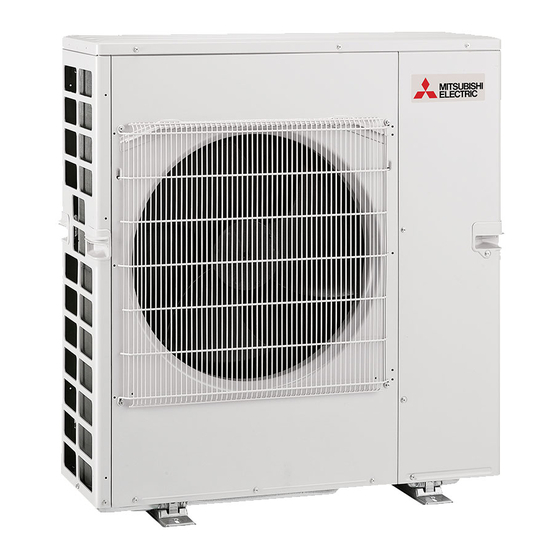
Summary of Contents for Mitsubishi Electric MXZ-6F120VGD
- Page 1 Split-type Air-Conditioner MXZ-6F120VGD For INSTALLER Installation Manual English • This manual only describes the installation of outdoor unit. When installing the indoor unit, refer to the installation manual of indoor unit.
-
Page 2: Table Of Contents
Required Tools for Installation CONTENTS Phillips screwdriver Flare tool for R32, R410A Level Gauge manifold for R32, R410A 1. BEFORE INSTALLATION ............1 Vacuum pump for R32, R410A Scale 2. OUTDOOR UNIT INSTALLATION ..........7 Utility knife or scissors Charge hose for R32, R410A 3. - Page 3 Voltage connecting wire unit / for multi system multi-system 220 V 60 Hz 4-core 3-core MXZ-6F120VGD 32 A 25 m / 80 m 15 m 25 / 80 230 V 50 Hz 4.0 mm 1.0 / 1.5 mm Maximum amount of...
- Page 4 FREE SPACE REQUIRED AROUND OUTDOOR UNIT Obstacles above Front (blowing) side open As long as space indicated When there is no obstacle in front and 100 or more in the figure is provided, it on the sides of the unit, it is allowed 200 or more to install the unit where an obstacle is is allowed to install the unit...
- Page 5 1-4-1. Minimum installation area for Outdoor units If you unavoidably install a unit in a space where all four sides are blocked or there are depressions, confirm that one of these situations (A, B or C) is satisfied. Note: These countermeasures are for keeping safety not for specification guarantee. A) Secure sufficient installation space (minimum installation area Amin).
- Page 6 1-4-2. Minimum installation area for Indoor units Install in a room with a floor area of Amin or more, corresponding to refrigerant quantity M (factory-charged refrigerant + locally added refrigerant). Install the indoor unit so that the height from the floor to the bottom of the indoor unit is h0; for wall mounted: 1.8 m or more;...
- Page 7 1-5. INSTALLATION DIAGRAM After the leak test, apply insulat- ing material tightly so that there ACCESSORIES is no gap. Check the following parts before installation. (1) Drain socket When the piping is to be attached to (2) Drain cap a wall containing metals (tin plated) or metal netting, use a chemically treated wooden piece 20 mm or thicker between the wall and the...
-
Page 8: Outdoor Unit Installation
2. OUTDOOR UNIT INSTALLATION 2-1. INSTALLING THE UNIT • Be sure to fix the unit’s legs with bolts when installing it. • Be sure to install the unit firmly to ensure that it does not fall by an earthquake or a gust. •... -
Page 9: Flaring Work And Pipe Connection
3. FLARING WORK AND PIPE CONNECTION 3-1. PRECAUTIONS FOR DEVICES THAT USE R32 REFRIGERANT • Use ester oil, ether oil, alkylbenzene oil (small amount) as the refrigeration oil applied to the flared sections. • Use C1220 copper phosphorus, for copper and copper alloy seamless pipes, to connect the refrigerant pipes. Use refrigerant pipes with the thicknesses specified in the table to the below. -
Page 10: Purging Procedures, Leak Test, And Test Run
4. PURGING PROCEDURES, LEAK TEST, AND TEST RUN 4-1. PURGING PROCEDURES AND LEAK TEST 1) Remove service port cap of stop valve on the side of the outdoor unit gas pipe. Compound pressure gauge (for R32, R410A) (The stop valves are fully closed and covered in caps in their initial state.) –0.101MPa *4 to 5 turns 2) Connect gauge manifold valve and vacuum pump to service port of stop valve... - Page 11 4-3. LOCKING THE OPERATION MODE OF THE AIR CONDITIONER (COOL, DRY, HEAT) • Description of the function: With this function, once the operation mode is locked to either COOL/DRY mode or HEAT mode, the air conditioner operates in that mode only. * Changing the setting is required to activate this function.
-
Page 12: Pumping Down
4-7. TEST RUN • Test runs of the indoor units should be performed individually. See the installation manual coming with the indoor unit, and make sure all the units operate properly. • If the test run with all the units is performed at once, possible erroneous connections of the refrigerant pipes and the indoor/outdoor unit connecting wires cannot be detected. - Page 16 HEAD OFFICE: TOKYO BUILDING, 2-7-3, MARUNOUCHI, CHIYODA-KU, TOKYO 100-8310, JAPAN VG79Y171H01...


Need help?
Do you have a question about the MXZ-6F120VGD and is the answer not in the manual?
Questions and answers