Advertisement
Quick Links
Advertisement

Related Manuals for Craftmade WCSD-100

Summary of Contents for Craftmade WCSD-100
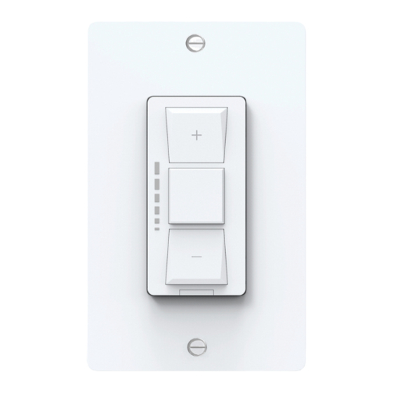
- Page 1 WCSD-100 Smart on/off Dimmer Switch Installation Guide...
- Page 2 WARNING: RISK OF ELECTRIC SHOCK This product installation requires handling 120 volt wiring. Follow each step carefully. If any concerns handling wiring, hire a qualified electrician. Ensure all work meets local and federal regulations.
- Page 3 Simple DIY Setup • Install your Craftmade Smart Switch. • Download the Craftmade Smart app. • Add your Craftmade Smart Switch the Craftmade Smart app.
-
Page 4: Compatibility Requirements
Compatibility Requirements • Rating 120V AC 60Hz. • Neutral wire required (wire is usually white or gray). • Ground wire required (wire is usually green, green with yellow stripe, or bare copper). • Wi-Fi 802.11 b/g/n @ 2.4 GHZ is required. •... -
Page 5: Parts Included
Parts Included Switch Wall Plate 4 Wire Nuts 4 Mounting Screws Line Load Ground Neutral Wire Labels... -
Page 6: Tools You Will Need
Tools you will need Philips Screwdriver Needle Nose Pliers (Recommended) Voltage Tester (Recommended) Allow 30 minutes to perform installation. - Page 7 Step 1 - Turn off the Power! • Turn off the power for the switch location at the circuit breaker box. • Test existing switch by toggling switch on/off, ensuring the lights do not turn on. • Now, follow these setup steps for a single gang switch.
- Page 8 3. Before disconnecting the wires from the wall, label each with the provided wire labels. a. Attention: Neutral and ground wires are required. If you don’t have either wire, the Craftmade Smart Switch cannot be installed. 4. Disconnect wires and remove the existing switch.
- Page 9 Step 2 - Remove your old switch...
-
Page 10: Step 3 - Connect The Wires
Step 3 - Connect the Wires 1. Connect the neutral (white) wire on the switch to neutral (white label) wire from the wall. 2. Connect the line (black) wire on the switch to the line (black label) wire from the wall. 3. - Page 11 Step 3 - Connect the Wires...
- Page 12 Step 4 - Fit wire into wall box 1. Neatly push the wires back into the box, rotating the switch so it’s oriented according to the image. Line Load Ground Neutral...
-
Page 13: Step 5 - Secure The Switch
Step 5 - Secure the Switch 1. Using a Philips screwdriver and screws provided, secure the switch to the wall until level and flush. 2. Screw on the faceplate onto the switch. - Page 14 Step 6 - Turn the Power Back On 1. After the switch is secured and the faceplate mounted, turn the power back on at the circuit breaker box. 2. At the switch, a green light will begin flashing inside the button indicated the device is wired correctly and the device is in setup mode.
- Page 15 Step 6 (continued) The green light will continuously flash until the switch is added to the Craftmade Smart App. If you need to start the process again to add to the Craftmade Smart App, you can depress the on/off paddle button for 5 seconds.
- Page 16 Congratulations! You’ve completed the Craftmade Smart Switch installation. Next... • Download the Craftmade Smart app • Add your Craftmade Smart Switch to the Craftmade Smart app • Set up your Alexa, Google voice assistant or Home Kit (optional)
- Page 17 Alternate Connection Procedure Smart mode networking Preconditions: Connect to the load, reset state (reset state at load mode and the white light will flash, long press switch 5S to reset the load) 1. Click “+” in the upper right corner (or click Add Device)
- Page 18 Alternate Connection Procedure (continued) 2. Select the device type as Switch (Wi-Fi)
- Page 19 Alternate Connection Procedure (continued) 3. Connect to Wi-Fi, enter the password of Wi-Fi account, and click “Next”.
- Page 20 Alternate Connection Procedure (continued) 4. The network is being distributed.
- Page 21 Alternate Connection Procedure (continued) 5. Your device should show successfully added.
- Page 22 Alternate Connection Procedure (continued) 6. Enter the device control page.
- Page 23 Additional Information and Warnings FCC Compliance Statement Compliance Notice: This equipment has been tested and found to comply with the limits for a Class B digital device, pursuant to part 15 of the FCC Rules. These limits are design - ed to provide reasonable protection against harmful interference in a residential installation.
- Page 24 CAN ICES-3 (B)/NMB-3(B) Model: model no WCSD-100 This device contains license-exempt transmitter(s)/receiver(s) that comply with Innovation, Science and Economic Development Canada’s license- exempt RSS(s). Operation is subject to the following two conditions: 1. This device may not cause interference. 2. This device must accept any interference, including interference that may cause undesired operation of the device.
- Page 25 CAUTION: FOR CONTROL OF INCANDESCENT OR LED LUMINAIRES ONLY. ATTENTION : POUR LA COMMANDE DE LUMINAIRES A INCANDESCENTS OU LED SEULEMENT 1. 1 Gang: 450 W incandescent or 150 W LED load, 2 Gang: 350W incandescent or 150 W LED load, 3 Gang: 300W incandescent or 150 W LED load. 1 Gang: 450 W de charge LED incandescente ou 150 W, 2 Gang: 350W incandescent ou 150 W decharge LED, 3 Gang: 300W incandescent ou 150 W de charge LED.
- Page 26 RF Exposure information: This equipment complies with FCC radiation exposure limits set forth for an uncontrolled environment. In order to avoid the possibility of exceeding the FCC radio frequency exposure limits, human proximity to the antenna shall not be less than 8 inches during normal operation.
- Page 27 CAUTION – To reduce the risk of overheating and possible damage to other equipment. Do not install to control a receptacle or motor-operated appliance or transformer-suppled appliance. For supply connections, use copper wire only rated at 75 degrees C.
Need help?
Do you have a question about the WCSD-100 and is the answer not in the manual?
Questions and answers