Table of Contents
Advertisement
Quick Links
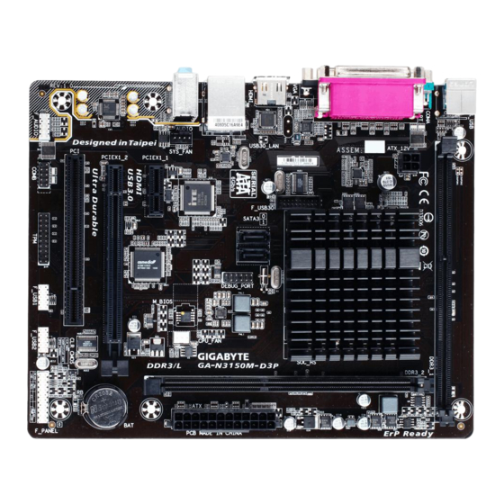
GA-N3150M-D3P
GA-N3050M-D3P
User's Manual
Rev. 1003
GA-N3150M-D3P
GA-N3050M-D3P
To reduce the impacts on global warming, the packaging materials of this product
are recyclable and reusable. GIGABYTE works with you to protect the environment.
For more product details, please visit GIGABYTE's website.
Advertisement
Table of Contents


Need help?
Do you have a question about the GA-N3150M-D3P and is the answer not in the manual?
Questions and answers