Table of Contents
Advertisement
Quick Links
Advertisement
Table of Contents

Related Manuals for Profoto Acute2R


Summary of Contents for Profoto Acute2R
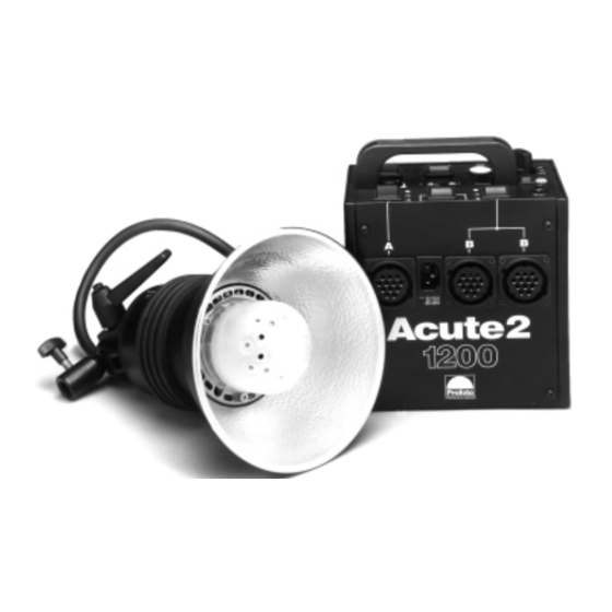
- Page 1 Acute2 manual Profoto, Stockholm, Sweden.
- Page 2 Warning Profoto generators and lamp heads are parts of a complete professional lighting system. Please read the instruction manual carefully before use. Flash tubes and modelling lamps emit considerable heat and may cause injury if not handled properly. Note, always unplug the lamp cable from the generator before changing the modelling lamp or flash tube.
-
Page 3: Table Of Contents
Technical data ....... 27 The Acute2 system consists of the following products: Generators:Acute2 1200, Acute2 2400 Heads: Acute2 head, Acute2 twin, Acute2 ring All Profoto reflectors and accessories fit the Acute2 system. -
Page 4: Thanks
There are glass covers with varying filtration, for greater diversity. The whole Acute2 system is modular. Every single reflector and accessory creates its special light and the unique Profoto focusing system offers you a possibility to create your own light with only a few different reflectors. - Page 5 Profotos founders Eckhard Heine och Conny Dufgran, At ”Photokina”,Cologne, Germany 1968 ”A photographer’s tools are a natural part of the crea- tive process. Like a painter’s brush, an artist’s chisel or a musician’s instrument, their form and design should reflect their function, they should have the right feel, and they should be aesthetically pleasing”.
-
Page 6: The Acute2 System Chart
Acute 2 Acute2 1200 Acute2 2400 Acute2 Flash Extension Cable Acute2 head Acute2 twin Narrow Beam travel Reflector Softlight Softlight ProGlobe Disc Reflector Silver Reflector white w/clips Reflector ProGlobe Adapter Honeycomb Glass w/Chimera Plate Grid 5 and 7 foot Reflector ProZoom ProFocus ProBox... - Page 7 The common denomi- Snoot 5°, 10° & nator is the lamp head diameter, which is the 20° Grid base of the Profoto line of products. The lines indicate the possible combinations that Profoto equipment offers.
-
Page 8: Acute2 Head
Acute2 head 1. UV reduced flash tube 2. Umbrella holder 3. Manoeuvre system with locking lever 4. Stand adapter 16mm (5/8") 5. Acute2 Glass Cover, frosted, UV-coated 6. Halogen modelling lamp, 250W, Mini-can E11 socket 7. Locking springs 8. Zoom reflector... -
Page 9: Acute2 Twin
Acute2 twin 1. UV reduced flash tubes 2. Umbrella holder 3. Manoeuvre system with locking lever 4. Stand adapter 16mm (5/8") 5. PB/Twin Glass Cover , frosted, UV-coated 6. Halogen modelling lamp, 500W, Mini-can E11 socket 7. Locking springs 8. Magnum Reflector... -
Page 10: The Flash Heads
The flash heads All Profoto lamp heads are designed for maximum light shap- ing purposes. The light source (both the flash tube and the mod- elling lamp) is mounted high and free in the flash head. This makes it easier for you to adjust the light and use your creativity. -
Page 11: Acute2 Head
Acute2 head The Acute2 head is fan cooled and it has an automatic voltage selector for the fan. The dimmer controlled modelling light is powered directly from the mains and it is therefore important to check that the rated voltage for the lamp corresponds with the mains supply. -
Page 12: Acute2 Twin
Acute2 twin The Acute2 twin is used to obtain even shorter flash duration, very quick recycling or to fire 4800 Ws out of one single head. An Acute2 twin has two flash tubes. As the flash duration is shorter at low power switch settings, and as only half of the desired power is used in each tube, consequently shorter flash duration is obtained. -
Page 13: Acute2 Ring
Acute2 ring The Acute2 ring is an entirely mobile source of light. The interior diameter of 100mm provides plenty of space for pro- fessional camera lenses. Since the camera holder can be tilted forward and backwards, as well as upwards and downwards, most cameras can be attached. -
Page 14: Nomenclature
Nomenclature 1. Power On/Off 9. Sound Switch 2. Modelling Light Dimmer for Group A 10. Slave (Photocell) Switch On/Off 3. Modelling Light Dimmer for Group B 11. Photocell and IR 4. Modelling Light Control Max/Dim/Off 12. A-Switch 5. Ready Lamp & Test Button 13. -
Page 15: Brief Instructions
17. Flash head socket (group A) 18. Mains connection 19. Flash head socket(group B) 20. Flash head socket(group B) Brief instructions • Check that the voltage you have selected on generator corresponds with the mains supply voltage • Check that the modelling lamp has the correct voltage •... - Page 16 Warning! Never use ordinary household extension cords to extend the length of the power cable. They may overheat. Contact your Profoto distributor for proper equipment. Connecting lamp heads One, two or three lamp heads can be connected to the sockets marked A, B and B (15).
-
Page 17: Energy Distribution
Energy distribution The energy can be controlled over a 6 f-stop range or 7 when using 2 heads connected to the B sockets. The energy output through the outlets A (17) and B (19,20) is controlled by the A+B / A<->B switch (13), the (12) (13) (14) - Page 18 Energy distribution One head 1. Connect the head to socket A. 2. Reduce the energy one f-stop by switching A+B / A<- >B switch to position A<- >B. 3. Further reduce the energy one or two f-stops by halving or quartering the energy with the A-switch.
- Page 19 4. Use the dial BRACKET for fine adjustments and to further reduce the energy by two f-stops. Three heads Symmetrical light distribution 1. Connect one head to each socket 2. Set the A+B / A< - >B switch in position A+B. The energy for the two groups is now added and then equally divided between the connected heads.
-
Page 20: Energy Distribution Acute2 Twin
Energy distribution Acute2 twin One generator 1. Connect the head sockets to the two B sockets on the generator. 2. Reduce the energy one f-stop by switching A+B / A<->B switch to position A<->B. 3. Further reduce the energy one or two f-stops by halving or quartering the energy with the B-switch. -
Page 21: Energy Control
Energy Control With the dial BRACKET (15) the total energy can, irrespective of the energy distribution, be reduced to 1/4, i.e. two f-stops. The flash duration, recycling and colour temperature is affect- ed by using the dial BRACKET. When using the bracketing dial (15) to reduce the energy you need to dump excess energy by pushing down the test button (5). - Page 22 Charging and recycling Check that the voltage selector (7) and the frequency - selector(8) matches the mains supply voltage. Turn on the main switch POWER (1). The recycling time is very short. Variations may occur depend- ing on the selected flash energy and the mains power supply. The shortest recycling time is obtained with low flash energy selected with the A-, B- and A+B / A<->B-switches and the BRACKET (15) dial.
- Page 23 The 5 metre sync cord can without restrictions be elongated with a sync extension cable. Sound signal The acoustic signal "beeps" when the unit is fully recycled. The signal can be turned on/off with the SOUND switch (9) Recycling Time With the button fast/slow (6) the recycling time can be adjusted to slow to preserve weak fuses or heavily loaded mains sup- plies.
-
Page 24: Gas Generator
230V. For more detailed information please see below or contact your local Profoto dealer. With a gas generator with an output of 3000W or more 2 Acute2 generators can be operated. - Page 25 Warranty All Profoto products are guaranteed for a period of 2 years, with the exception of flash tubes, glass covers and modelling lamps. Reliability Testing – The R-test The Profoto R-test guarantees that all products leaving the factory meet the very high standards required of professional equipment by professional photographers.
-
Page 26: Troubleshooting Guide
Troubleshooting Guide Problem Action • No ready lamp but ready sound • Change ready lamp • No flash • Check flash tube • Fuses keep blowing • Reduce recycling speed • Continuous red light in Photocell • Generator is overheated •... -
Page 27: Technical Data
Technical data Guide no. In meter/feet at 100 ASA Acute2 1200 Acute2 2400 Magnum reflector 50 degree. 128/420 180/592 Zoom reflector 64/210 90/295 Umbrella 32,5/126 45,5/180 Power requirements • 90-130 VAC, 50 or 60 Hz. 15 Amps recommended for 2 units. •... - Page 28 Profoto AB, P .O. Box 2023, SE-128 21 Skarpnäck, Sweden Tel +46 (0)8-447 53 00, Fax +46 (0)8-447 53 20 www.profoto.com info@profoto.se Product codes, descriptions and included components may vary from market to market around the world. Please consult your importer for specific information.
Need help?
Do you have a question about the Acute2R and is the answer not in the manual?
Questions and answers