Table of Contents
Advertisement
Quick Links
Advertisement
Table of Contents

Subscribe to Our Youtube Channel
Summary of Contents for MAKINEX PHT-40
- Page 1 Rev 0917...
-
Page 2: Table Of Contents
CONTENTS FORWARD ........................ 3 DISCLAIMER ......................3 1. INTRODUCTION ....................4 2. SAFETY INFORMATION ..................5 2.1 Training ......................5 2.2 Preparation ....................... 5 2.3 Operation ......................5 2.4 Maintenance and Charging ................6 2.4.1 Adjusting brakes ..................6 2.4.2 Securing nose hook onto jib .............. -
Page 3: Forward
MAKINEX. The information contained in this manual was based on machines in production at the time of publication. MAKINEX reserves the right to change any portion of this information without notice. All rights, especially copying and distribution rights are reserved. -
Page 4: Introduction
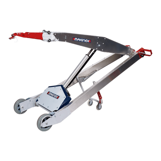
1. INTRODUCTION The PHT-140 device is a hand truck with a powered lifting arm which can be fitted with various attachment tools. The basic PHT-140 device is configured in combination with a hook attachment fitted to the lifting arm. Typically, the device is used for loading small machinery fitted with a lifting eye onto or off vehicles –... -
Page 5: Safety Information
2. SAFETY INFORMATION 2.1 Training • To access PHT-140 training video scan QR code or go to www.youtube.com/watch?v=MN5TgT-I49I • All operators should be trained. The owner is responsible for training the users. • Never let children or untrained people operate or service the equipment. •... -
Page 6: Maintenance And Charging
• Do not lift an item bulky enough to hit the lift arm in lifted position - some fixed lifting eyes may be positioned so that parts of the load hit the lift arm in raised position. • Do not lean beyond balanceable point for user as per training procedure. •... - Page 7 To tighten or loosen PHT-140 brakes: 1. Lie your powered hand truck down on a bench or flat surface with folding support wheels folded to take load off the large wheels. 2. Ensure brakes are disengaged. 3. Remove side plate on right hand side of unit using Phillips head screw driver. Inside this panel you will find a pictogram (below) demonstrating steps for adjustment 4.
- Page 8 6. Test brakes and observe pad is depressing rubber on wheel. When brakes are disengaged ensure that both brakes are equal distance between brake pad and wheel rubber. The pad should not be touching the rubber. 7. Re-tighten retainer nut after desired adjustment is achieved. 8.
-
Page 9: Securing Nose Hook Onto Jib
2.4.2 Securing nose hook onto jib Insert the tabs of the nose hook assembly into the jibs mounting slots and secure using an M10x130mm Hex bolt & M10 Nyloc nut. Page 9 of 37... - Page 10 2.5 Transport and Storage • Do not leave machine propped against wall (in flattened state) where it could fall over and cause injury or damage, always lock wheels by applying brakes. Store clear of bystanders and make sure it’s not obstructing fire exits or walk ways •...
-
Page 11: Operation
3. OPERATION 3.1 Controls/Layout Removable Nose Cone Safety Locking Hook Powered Lifting Arm Linear Actuator Handle Brake Adjust compartment Brake Removable Battery Locking Plunger Folding Support Lift arm control Wheels Brake release lever On/Off Switch Page 11 of 37... -
Page 12: General
3.2 General • Hook Reach is the horizontal distance 3.2.1 Control Hook Reach between the wheel axle and the hook. Being able to ‘reach out’ with the hook is • fundamental to the operation and function of the PHT-140 device. •... -
Page 13: Steering While Unloaded
3.2.4 Steering while unloaded Hands pressed down and the device supported on rear wheels Front wheels off ground allows the device to pivot on back wheels which reduces turning circle. • With rear wheels down, the machine can be easily pushed along in a straight line with no weight on the user’s hands. -
Page 14: Loading And Unloading At Ground Level
3.2.5 Loading and unloading at ground level This section explains how to get a load at ground level engaged onto the device and in a hands neutral position. A hands neutral position is when the device is loaded and the load is balanced against the weight of the device resulting in minimal balancing force required by the hands. -
Page 15: Hook Operation
3.2.6a Hook Operation • Hook operation is designed to enable one man hook engagement and disengagement in a fixed lifting point. • For flexible lift point such as a sling, second person may be required to engage or disengage the hook from the sling •... -
Page 16: Hook Operation
3.2.6b Hook Operation Push the tab upwards and the spring on the top of the hook will lock into the groove on the catch In circumstances where the hook must be locked for safety, a safety catch is available to use. TO RELEASE, PUSH THE TAB IN THE REVERSE DIRECTION Page 16 of 37... -
Page 17: Operating Brakes
3.2.7 Operating Brakes • Brakes work like the park brakes on a car • Once engaged, it will automatically stay on until released • Brake Engaged Brake Disengaged Brake Catch Release Brake Handle Engaging Brake • Releasing Brake Brakes can be easily applied by pulling the brake handle towards the handle bar Activating Brake... -
Page 18: Ground Conditions
3.2.8 Ground Conditions • Firm ground is required for loading and unloading with the PHT-140 device. Concrete, asphalt, rolled road base are suitable. • Small stones or bumps can reduce the ability to manoeuvre the loaded device into a good position for executing a lift. -
Page 19: Lift Technique
3.3 Lift Technique 3.3.1 Raising & lowering load • These figures show different load heights in the hands neutral position • Keep device stationary while raising load. • Once load height clear of platform, carefully move wheels closer. • Apply brakes and begin the unload procedure. •... -
Page 20: Loading & Unloading At Height
3.3.2 Loading & Unloading at height • Be certain the platform can take the weight of the load. • Only attempt to transfer the load to an elevated platform that can take the weight. Have a firm footing – device can pull user towards load in high load, high reach situations. •... - Page 21 • Once load is above platform and safely beyond edge – lower the lifting arm to lower the load onto platform and take weight off hook • Disengage brake and remove hook • See section 3.2.6 for Hook Operation detail Figure shows backing device away from unload procedure whilst lowering the lifting arm REVERSE SEQUENCE –...
-
Page 22: Increased Risk Position
3.3.3 Increased Risk Position Figure shows hands raised above Chest Height If wheels were closer to the platform the operator would require less Reach • The above position shows extended reach and hands raised above chest height. • It is in this region that heavy load can become unmanageable because of the force required to control the handles. -
Page 23: Charging
3.4 Charging • The 18V Lithium Ion battery can be recharged with an external charger. • Top up battery regularly. • Full charge from the low battery level will take 2 hours. • A full battery will sustain around 45 load and unload cycles at 90kg. The external charger will not over charge battery –... -
Page 24: Transport And Storage
If linear actuator or power fails preventing the ability to lower the Powered Lifting Arm, follow these instructions: • If lifting arm is low enough, place load on the ground and disengage it, if lifting arm is close to a bench or platform, place load on the platform and disengage it. •... - Page 25 Slide machine on or off utility vehicle Up to 25kg lift • When using device on a day to day basis – time and battery power is saved by leaving the device as illustrated between uses. Page 25 of 37...
-
Page 26: Load And Reach Data
4. LOAD AND REACH DATA Unloaded, Pre-Pick Up MW Weight of PHT-140 device (40kg) Balancing Force applied by Hands Weight of the Load (up to 140kg *120kg for all other attachments) Reach – horizontal distance from wheel axle to hook •... -
Page 27: Slope Guide
5. SLOPE GUIDE Loading / unloading across-hill >CAUTION< Loading / unloading downhill Loading / unloading uphill >CAUTION< Max - 2% or 1 degree –VIRTUALLY FLAT Max - 2% or 1 degree–VIRTUALLY FLAT Max - 4% or 3 degrees • • One wheel 13mm higher than other rear wheel 18mm lower than front when grounded Increased risk... -
Page 28: Quick Reference Hazard Assessment
6. QUICK REFERENCE HAZARD ASSESSMENT PRODUCT RISK / HAZARD ASSESSMENT TABLE PRODUCT NAME: PHT-140 Assessment Carried Out Michael Chen MANUFACTURER: MAKINEX Document Revision OPERATOR COMPETENCY: PLANT LICENCE NOT REQUIRED Date Created: 21/01/2016 TYPE / NATURE OF RISK or HAZARD LIKELIHOOD CONSEQUENCE RISK LEVEL... - Page 29 LOADING PHT-140 ONTO UTE MAJOR MEDIUM CHECK AND FOLLOW USER MANUAL STRAIN CAUSING BACK INJURY UNLIKELY ALWAYS LIFT CLEAR OF BYSTANDERS ENSURE BATTERY IS FULLY CHARGED BEFORE OPERATING. BATTERY DISCHARGED AFTER CHECK THE BATTERY FOR WEAR SIGNS; DO NOT USE IF LEAKING LIFTING THE LOAD LEAVING THE UNLIKELY MINOR...
-
Page 30: Safety And Instruction Decal
7. SAFETY AND INSTRUCTION DECAL Page 30 of 37... -
Page 31: Technical Data And Specifications
8. TECHNICAL DATA AND SPECIFICATIONS 1986 1900 MACHINE SPECIFICATIONS Lift Capacity Up to 140kg / 308lbs (120kg / 264lbs for all other attachments) Linear Actuator 12V 25Amp Hook Height Range Ground to 1.9m Total 40kg ▪ Handle end - 15kg Weight of Machine ▪... - Page 32 CHARGER SPECIFICATIONS Page 32 of 37...
-
Page 33: Declaration Of Conformity
9. DECLARATION OF CONFORMITY Page 33 of 37... -
Page 34: Limited Warranty
MAKINEX product in peak operating condition. MAKINEX warrants each new Powered hand truck to be free from defects in material and workmanship under normal domestic and industrial use and service for the period specified below, conditional to the limitations and exclusions printed on this page. -
Page 35: Warranty Exclusions
Claim Procedure: Contact MAKINEX by phone or email informing us of your machines problem or defect. Page 35 of 37... - Page 36 This warranty only applies to the original purchaser and is not transferable. It is the responsibility (and cost) of MAKINEX or our appointed agent to return the machine to be repaired or replaced under warranty to the consumer- this is valid for domestic territories only (e.g.
-
Page 37: Contact Information
EMAIL sales@makinex.com.cn ADDRESS Suzhou Industrial Park Xinghai Street on the 16th Jinying Pioneering Park, 2nd Floor, Area C Or your nearest MAKINEX distributor We have very knowledgeable, experienced staff to assist you with help and advice. Page 37 of 37...
Need help?
Do you have a question about the PHT-40 and is the answer not in the manual?
Questions and answers