Table of Contents
Advertisement
Quick Links
Advertisement
Table of Contents

Subscribe to Our Youtube Channel
Related Manuals for Cameo WLN-2217


Summary of Contents for Cameo WLN-2217
- Page 1 300Mbps Wireless N Gigabit Router WLN-2217 CAMEO User’s Guide...
- Page 2 Federal Communication Commission Interference Statement This equipment has been tested and found to comply with the limits for a Class B digital device, pursuant to Part 15 of the FCC Rules. These limits are designed to provide reasonable protection against harmful interference in a residential installation. This equipment generates, uses and can radiate radio frequency energy and, if not installed and used in accordance with the instructions, may cause harmful interference to radio communications.
- Page 3 Europe – EU Declaration of Conformity This device complies with the essential requirements of the R&TTE Directive 1999/5/EC. The following test methods have been applied in order to prove presumption of conformity with the essential requirements of the R&TTE Directive 1999/5/EC: EN60950-1: 2010 Safety of Information Technology Equipment EN 50385: 2002...
- Page 4 [Jméno výrobce] tímto prohlašuje, že tento [typ zařízení] je ve shodě se základními požadavky a dalšími Česky [Czech] příslušnými ustanoveními směrnice 1999/5/ES. Undertegnede [fabrikantens navn] erklærer herved, at følgende udstyr [udstyrets typebetegnelse] overholder de Dansk [Danish] væsentlige krav og øvrige relevante krav i direktiv 1999/5/EF. Hiermit erklärt [Name des Herstellers], dass sich das Gerät [Gerätetyp] in Übereinstimmung mit den Deutsch grundlegenden Anforderungen und den übrigen einschlägigen Bestimmungen der Richtlinie 1999/5/EG...
-
Page 5: Table Of Contents
TABLE OF CONTENT ..................1 BOUT UIDE Purpose........................................1 Terms/Usage ......................................1 Overview of this User’s Guide................................1 ...................2 NTRODUCTION Applications: ......................................2 Supported Features: ....................................3 ................4 NPACKING AND ETUP Unpacking ......................................4 Setup ........................................4 ................5 ARDWARE NSTALLATION Front Panel ......................................5 Rear Panel ...................................... - Page 6 Virtual Server....................................42 Special AP....................................... 43 DMZ........................................ 45 Firewall settings ....................................46 System Setting ....................................47 Password ......................................47 Time ........................................ 48 Device Information ..................................49 Log ........................................50 Log Setting...................................... 51 Statistic......................................52 Restart ......................................53 Firmware ......................................54 Configuration ....................................
-
Page 7: About This Guide
ABOUT THIS GUIDE Congratulations on your purchase of this IEEE 802.11b/g/n Wireless Broadband Router. This integrated access device combines Internet gateway functions with wireless LAN and Fast Ethernet switch. It provides a complete solution for Internet surfing and office resource sharing, and it is easy to configure and operate for every user. -
Page 8: Introduction
INTRODUCTION With the explosive growth of the Internet, accessing information and services at any time, day or night has become a standard requirement for most people. The era of the standalone PC is waning. Networking technology is moving out of the exclusive domain of corporations and into homes with at least two computers. -
Page 9: Supported Features
Supported Features: High speed data transfer rate NAT for sharing 1 IP address to all LAN/WLAN users. PPPoE and PPTP protocol for Dial-Up ADSL. 64/128 bit WEP Encryption WPA-PSK, WPA2-PSK, WPA, WPA2 security DHCP Server / Client. UPnP (Universal Plug and Play). WPS (Wi-Fi Protected Setup) Virtual Server mapping. -
Page 10: Unpacking And Setup
UNPACKING AND SETUP This chapter provides unpacking and setup information for the IEEE 802.11b/g/n Wireless Broadband Router. Unpacking Open the box of the WLAN Router and carefully unpack it. The box should contain the following items: One IEEE 802.11b/g/n Wireless Broadband Router One CD contain User’s Guide Two 2dBi gain dipole antenna One external power adapter... -
Page 11: Hardware Installation
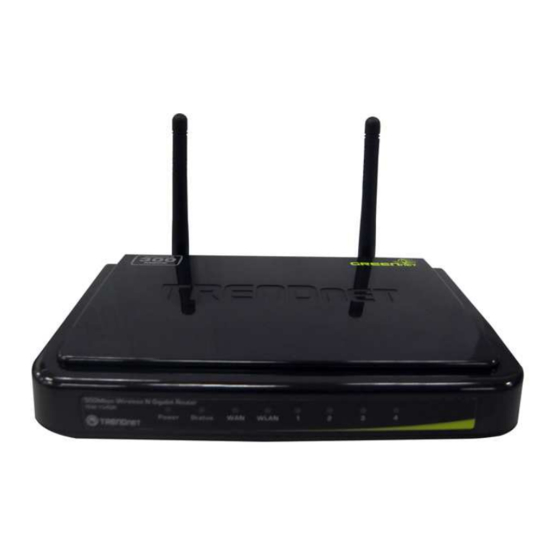
HARDWARE INSTALLATION Front Panel The figure below shows the front panel of the IEEE 802.11b/g/n Wireless Broadband Router. Front Panel POWER This indicator lights green when the hub is receives power, otherwise it is off. SYSTEM This indicator blinking green means the WLAN Router is working successfully. Otherwise, this indicator always on or off means the function of the WLAN Router has failed. - Page 12 LAN (Link/ACT) These indicators light green when the LAN ports were connected successfully. These indicators blinking green while the LAN ports were accessing data.
-
Page 13: Rear Panel
Rear Panel The figure below shows the rear panel of the IEEE 802.11b/g/n Wireless Broadband Router. Rear Panel Antenna There is two 2dBi gain antennas on the rear panel for wireless connection. LAN (1-4) Four RJ-45 10/100Mbps Auto-MDIX ports for connecting to either 10Mbps or 100Mbps Ethernet connections. -
Page 14: Side Panel
Side Panel The figure below shows the side panel of the IEEE 802.11b/g/n Wireless Broadband Router. Side Panel Push this button to execute the Wi-Fi Protected Setup process. -
Page 15: Hardware Connections
Hardware connections Connecting the WLAN Router 1. Plug in one end of the network cable to the WAN port of the WLAN Router. 2. Plug in the other end of the network cable to the Ethernet port of the xDSL or Cable modem. -
Page 16: Pc Network Tcp/Ip Setting
PC NETWORK TCP/IP SETTING The network TCP/IP settings differ based on the computer’s operating system (Win95/98/ME/NT/2000/XP) and are as follows. Windows 95/98/ME 1. Click on the “Network neighborhood” icon found on the desktop. 2. Click the right mouse button and a context menu will be show. 3. -
Page 17: Windows 2000
6. Select “None” for the “Gateway address” field. Windows 2000 Double click on the “My Computer” icon on the desktop. When “My Computer” window opens, open the “Control Panel” and then open the “Network dialup connection” applet. Double click on the “Local area network connection” icon. Select “Properties”... -
Page 18: Windows Xp / Vista
Windows XP / Vista Point the cursor and click the right button on the “My Network Place” icon. Select “properties” to enter the TCP/IP setting window. 1. Set “IP address” to “Obtain an IP address automatically.” 2. Set “DNS” to “Obtain DNS server address automatically.”... -
Page 19: Configuration
CONFIGURATION First make sure that the network connections are functioning normally. This WLAN Router can be configured using Internet Explorer 5.0 or newer web browser versions. Login to the WLAN Router through Wireless LAN Before configuring the WLAN Router through WLAN, make sure that the SSID, Channel and the WEP is set properly. -
Page 20: Setup Wizard
Setup Wizard Setup wizard is provided as part of the web configuration utility. User can simply follow the step-by-step process to get the wireless Router configuration ready to run in 6 easy steps by clicking on` the “Wizard” button on the function menu. The following screen will appear. - Page 21 Step 2: Choose time zone Select the time zone from the drop down list. Please click “Next” to continue. Step 3: Set LAN connection and DHCP server Set user’s IP address and mask. The default IP is 192.168.1.1. If the user chooses to enable DHCP, please click “Enable”.
- Page 22 Obtain IP automatically (DHCP client): If the user has enabled DHCP server, choose "Obtain IP automatically (DHCP client)" to have the WLAN Router assign IP addresses automatically.
- Page 23 Fixed IP Address: If the Internet Service Provider (ISP) assigns a fixed IP address, choose this option and enter the assigned WAN IP Address, WAN Subnet Mask, WAN Gateway Address and DNS Server Addresses for the WLAN Router.
- Page 24 PPPOE PPPoE to obtain IP automatically: If connected to the Internet using a PPPoE (Dial-up xDSL) connection, and the ISP provides a User Name and Password, then choose this option and enter the required information.
- Page 25 PPPoE with a Specify IP address: If connected to the Internet using a PPPoE (Dial-up xDSL) connection, and the ISP provides a User Name, Password and a Fixed IP Address, choose this option and enter the required information.
- Page 26 PPTP: If connected to the Internet using a PPTP xDSL connection, enter your IP, Subnet Mask, Gateway, Server IP, PPTP Account and PPTP Password.
- Page 27 L2TP: If connected to the Internet using a L2TP (Dial-up xDSL) connection and the ISP provides a Server IP, Account and Password information, choose this option and enter the required information.
- Page 28 Big Pond Cable(Australia): If your ISP is Big Pond Cable, the ISP will provide a User Name, Password, Authentication Server and Login Server IP (Optional). Choose this option and enter the required information.
- Page 29 Step 5: Set Wireless LAN connection Click “Enable” to enable Wireless LAN. If user enables the Wireless LAN, type the SSID in the text box and select a communications channel. The SSID and channel must be the same as wireless devices attempting to connect to the WLAN Router. (When in FCC domain, you could chose ch1~ch11;...
-
Page 30: Wan Setting
WAN Setting This function enables users to set up the WLAN Router WAN connection, specify the IP address for the WAN, add DNS numbers, and enter the MAC address. Connection Type: Select the connection type, either DHCP client, Fixed IP or PPPoE, PPTP, L2TP or BigPond from the drop-down list. -
Page 31: Pppoe With Obtain Ip Automatically
DNS 1/2: Manually specific DNS server IP address. For the Obtain IP Automatically mode, leave 0.0.0.0 hear, the DHCP server will provides DNS server automatically. Clone MAC Address: If your ISP requires you to enter a specific MAC address, please enter it in. The Clone MAC Address button is used to copy the MAC address of your Ethernet adapter to the Router. -
Page 32: Pppoe With Specify Ip
PPPoE with Specify IP If connected to the Internet using a PPPoE (Dial-up xDSL) Modem, the ISP will provide a Password, User Name and a Specify IP Address, choose this option and enter the required information. -
Page 33: Pptp/L2Tp With Obtain Ip Automatically
PPTP/L2TP with Obtain IP Automatically If connected to the Internet using a PPTP/L2TP (Dial-up xDSL) connection, enter the your Server IP, PPTP/L2TP Account and PPTP/L2TP Password, if your ISP has provided you with a DNS IP address, enter it in the DNS field, otherwise, leave it zero. -
Page 34: Bigpond Cable
BigPond Cable If your ISP is Big Pond Cable, the ISP will provide a User Name, Password, Authentication Server and Login Server IP (Optional). Choose this option and enter the required information. Dynamic DNS: This synchronizes the DDNS server with your current Public IP address when you are online. -
Page 35: Wireless Setting
Wireless setting This section enables user to set wireless communications parameters for the router's wireless LAN feature. Basic This page allow user to enable and disable the wireless LAN function, create a SSID, and select the channel for wireless communications. Enable/Disable: Enables or disables wireless LAN via the WLAN Router. -
Page 36: Security
Channel Width: Select the Channel Width: Auto 20/40 - This is the default setting. Select if you are using both 802.11n and non-802.11n wireless devices. 20MHz - Select if you are not using any 802.11n wireless clients. SSID Broadcast: While SSID Broadcast is enabled, all wireless clients will be able to view the WLAN Router’s SSID. - Page 37 WEP: Open System and Shared Key requires the user to set a WEP key to exchange data with other wireless clients that have the same WEP key. WEP Key Format: Select the key format from the drop-down list HEX or ASCII. WEP Key Length: Select the level of encryption from the drop-down list.
- Page 38 If WPA, WPA2 or WPA-Auto EAP is selected, the above screen is shown. Please set the length of the encryption key and the parameters for the RADIUS server. Cipher Type: Select the cipher type for TKIP or AES encryption, Selected Auto for auto detects the cipher type.
-
Page 39: Advanced
Advanced This function enables user to configure advanced wireless functions. Beacon Interval: Type the beacon interval in the text box. User can specify a value from 25 to 1000. The default beacon interval is 100. RTS Threshold: Type the RTS (Request-To-Send) threshold in the text box. This value stabilizes data flow. -
Page 40: Wi-Fi Protected Setup
Wi-Fi Protected Setup This screen enables users to configure the Wi-Fi Protected Setup function. WPS: Enable or Disable the WPS (Wi-Fi Protected Setup) function Status: Display the state (Un-configured State/Configured State) information of WPS. Self-PIN Number: Display the default PIN number of WLAN Router. Client PIN Number: Type Client PIN number the client uses to negotiate with WLAN Router via WPS protocol. -
Page 41: Lan Setting
LAN Setting The function enables user to configure the LAN port IP address & DHCP Server. Basic This page leads to set LAN port properties, such as the host name, IP address, and subnet mask. Host Name: Type the host name in the text box. The host name is required by some ISPs. -
Page 42: Dhcp
DHCP DHCP Server: Enables the DHCP server to allow the router to automatically assign IP addresses to devices connecting to the LAN. DHCP is enabled by default. DHCP Server Start IP: Type an IP address to serve as the start of the IP range that DHCP will use to assign IP addresses to all LAN devices connected to the router. - Page 43 Dynamic DHCP List: All dynamic DHCP client computers are listed in the table and providing the Host name, IP address, and MAC address and Expired Time of the client.
-
Page 44: Access Control Setting
Access Control Setting This access control enables you to define access restrictions, set up protocol and IP filters, create virtual servers, define access for special applications such as games, and set firewall rules. Filter Using filter to deny or allow the users to access. Five types of filters to select: MAC, IP Filter, URL blocking, Domain blocking and Protocol filter. - Page 45 (Note: Click anywhere in the item. Once the line is selected, the fields automatically load the item's parameters, which you can edit.) Name: Type the name of the user to be permitted/denied access. MAC Address: Type the MAC address of the user's network interface. Add: Click to add the user to the list at the bottom of the page.
- Page 46 Disable: Disable the Domain/URL Blocking function. Allow: Allow users to access all domains in the “Domains List”. Deny: Deny users to access all domains in the “Domains List”. Blocked/Permitted Domains/URL: List domains you will Blocked or Permitted. Apply: Click to add domain to the Blocked/Permitted Domains/URL list. Delete: Select a Domain/URL from the table at the bottom of the list and click Delete to remove the Domain/URL.
- Page 47 Enable: Click to enable or disable the IP address filter. Name: Type the name of the user to be denied access. Protocol: Select a protocol (TCP or UDP) to use for the virtual server. Port: Type the port range of the protocol. IP Range: Type the IP range.
-
Page 48: Virtual Server
Virtual Server This screen enables users to create a virtual server via the WLAN Router. If the WLAN Router is set as a virtual server, remote users requesting Web or FTP services through the WAN are directed to local servers in the LAN. The WLAN Router redirects the request via the protocol and port numbers to the correct LAN server. -
Page 49: Special Ap
Special AP This screen enables users to specify special applications, such as games which require multiple connections that are blocked by NAT. The special applications profiles are listed in the table at the bottom of the page. Note: When selecting items in the table at the bottom, click anywhere in the item. The line is selected, and the fields automatically load the item's parameters, which user can edit. - Page 50 Protocol: Select the protocol (TCP, UDP, or ICMP) that can be used by ● the incoming communication. Port: Type the port number that can be used for the incoming ● communication. Add: Click to add the special application profile to the table at the bottom of the screen.
-
Page 51: Dmz
This screen enables users to create a DMZ for those computers that cannot access Internet applications properly through the WLAN Router and associated security settings. Note: Any clients added to the DMZ exposes the clients to security risks such as viruses and unauthorized access. -
Page 52: Firewall Settings
Firewall settings A firewall protects your network from the outside world, this screen enables users to setup the simple firewall function on the wireless router. Endpoint Independent: Any incoming traffic sent to an open port will be forwarded to the application that opened the port. Address Restricted: Incoming traffic must match the IP address of the outgoing connection. -
Page 53: System Setting
System Setting This system setting enables users to change password, set the device time, view the device information, restart the system, save and load different settings as profiles, restore factory default settings, upgrade the firmware, and ping remote IP addresses….etc. Password This function enables users to set administrative and user passwords. -
Page 54: Time
Time This function enables users to set the time and date for the WLAN Router's real- time clock, select properly time zone, and enable or disable daylight saving. Local Time: Displays the local time and date. Time Zone: Select the time zone from the drop-down list. Synchronize the clock with NTP Server: Enable or disable the WLAN Router automatically adjust the system time from NTP Server. -
Page 55: Device Information
Device Information This function enables users to view the WLAN Router’s WAN, Wireless, LAN and System configurations. WAN: This section displays the WAN interface configuration including the MAC address, Connection status, DHCP client status, IP address, Subnet mask, Default gateway, and DNS. Wireless: This section displays the wireless configuration information, including the MAC address, the Connection status, SSID, Channel and Authentication type. -
Page 56: Log
This function enables users to view a running log of Router system statistics, events, and activities. The log displays up to 200 entries. Older entries are overwritten by new entries. The Log screen commands are as follows: Click “First Page” to view the first page of the log Click “Last Page”... -
Page 57: Log Setting
Log Setting This function enables users to set Router Log parameters. SMTP Authentication: Selected the Enabled if the SMTP server need for authentication, fill in account name and password in SMTP Account field and SMTP Password field. SMTP Account: If the SMTP Authentication enabled, fill in the SMTP account name here. -
Page 58: Statistic
Debug Information: Displays information related to errors and system malfunctions. Attacks: Displays information about any malicious activity on the network. Dropped Packets: Displays information about packets that have not been transferred successfully. Notice: Displays important notices by the system administrator. Statistic This function displays a table that shows the rate of packet transmission via the WLAN Router’s LAN, WAN and Wireless ports (in bytes per second). -
Page 59: Restart
Restart Click “Restart” to restart the system in the event the system is not performing correctly. -
Page 60: Firmware
Firmware This function enables users to keep the WLAN Router firmware up to date. Please follow the below instructions: Download the latest firmware from the manufacturer's Web site, and save it to disk. Click “Browse” and go to the location of the downloaded firmware file. Select the file and click “Upgrade”... -
Page 61: Configuration
Configuration This function enables users to save settings as a profile and load profiles for different circumstances. User can also load the factory default settings, and run a setup wizard to configure the WLAN Router and Router interface. -
Page 62: Upnp
UPnP This function enables users to enable or disable the UPnP function on the WLAN Router. UPnP: Select to enable or disable the UPnP function on the WLAN Router. UPnP is short for Universal Plug and Play that is a networking architecture that provides compatibility among networking equipment, software, and peripherals. -
Page 63: Ping Test
Ping Test The ping test enables users to determine whether an IP address or host is present on the Internet. Type the host name or IP address in the text box and click Ping button to start the Ping test. -
Page 64: Remote Management
Remote Management This function enables users to set up remote management. Using remote management, the WLAN Router can be configured through the WAN via a Web browser. A user name and password are required to perform remote management. HTTP: Enables users to set up HTTP access for port number, and Remote IP Range for remote management. -
Page 65: Technical Specifications
TECHNICAL SPECIFICATIONS General Standards IEEE 802.3u 100BASE-TX Fast Ethernet IEEE 802.11n 2.0; IEEE 802.11g; IEEE 802.11b Protocol CSMA/CA with ACK Radio Technology DSSS/OFDM Data Transfer Rate 802.11n mode: up to 300Mbps (auto sense) 802.11g mode: up to 54Mbps (auto sense) 802.11b mode: up to 11Mbps (auto sense) Ethernet: 10Mbps (half duplex), 20Mbps (full-duplex) Fast Ethernet: 100Mbps (half duplex), 200Mbps (full- duplex)
Need help?
Do you have a question about the WLN-2217 and is the answer not in the manual?
Questions and answers