Table of Contents
Advertisement
Quick Links
Advertisement
Table of Contents

Subscribe to Our Youtube Channel
Summary of Contents for Fortec Star ET876
- Page 2 Manual iBASE ET876 COM Express® Mini Modul with Intel® Atom™ x7/x5/ Pentium®/ Celeron® Apollo Lake Processor QC x7/ E3950, QC x5/ E3940, DC x5/ E3930 The information contained in this document has been carefully researched and is, to the best of our knowledge, accurate.
- Page 3 ET876 Series COM Express Type 10 Module Atom™ x7/x5 SoC ® With Intel User’s Manual Version 1.0 (June 2020)
- Page 4 Trademarks All the trademarks, registrations and brands mentioned herein are used for identification purposes only and may be trademarks and/or registered trademarks of their respective owners. ET876 Series User’s Manual...
- Page 5 0.1% by weight (1000 ppm) except for cadmium, limited to 0.01% by weight (100 ppm). • Lead (Pb) • Mercury (Hg) • Cadmium (Cd) • Hexavalent chromium (Cr6+) • Polybrominated biphenyls (PBB) • Polybrominated diphenyl ether (PBDE) ET876 Series User’s Manual...
- Page 6 Danger of explosion if the internal lithium-ion battery is replaced by an incorrect type. Replace only with the same or equivalent type recommended by the manufacturer. Dispose of used batteries according to the manufacturer’s instructions or recycle them at a local recycling facility or battery collection point. ET876 Series User’s Manual...
- Page 7 Software in use (such as OS and application software, including the version numbers) If repair service is required, you can download the RMA form at http://www.ibase.com.tw/english/Supports/RMAService/. Fill out the form and contact your distributor or sales representative. ET876 Series User’s Manual...
-
Page 8: Table Of Contents
Chipset Settings ................38 Security Settings ................42 Boot Settings ..................45 Save & Exit Settings ................46 Appendix ..................47 I/O Port Address Map ................ 48 Interrupt Request Lines (IRQ) ............51 Watchdog Timer Configuration ............53 ET876 Series User’s Manual... - Page 9 This page is intentionally left blank. ET876 Series User’s Manual...
-
Page 11: Chapter 1 General Information
Chapter 1 General Information The information provided in this chapter includes: • Features • Packing List • Optional Accessories • Specifications • Block Diagram • Product View • Board Dimensions... -
Page 12: Introduction
Introduction ® ET876 is a COM Express Type 10 module with Intel Atom™ x7/x5 (QC / DC) processor. It comes with type 10 pinouts and complies with the PICMG COM.0 Rev.3.0 specifications for ultra-low power consumption. This product features LPDDR4 memory slots, and provides DDI display and LVDS or eDP interface connection, and high-speed I/O such as USB 3.0, SATA III and... -
Page 13: Packing List
• This User’s Manual Optional Accessories IBASE provides optional accessories as follows. Please contact us or your dealer if you need any. • Heat spreader (HSET876-X-1 for ET876-X7/ X5Q/ X5) Specifications Product Name ET876 • Windows 10 (64-bit) Operating System •... - Page 14 With Intel Atom™ x7/x5: -40 ~ 85°C (-40 ~ 185°F) Temperature • Storage: -40 ~ 90 °C (-40 ~ 194°F) Relative 90 %, non-condensing at 60°C Humidity All specifications are subject to change without prior notice. ET876 Series User’s Manual...
-
Page 15: Block Diagram
General Information Block Diagram ET876 Series User’s Manual... -
Page 16: Product View
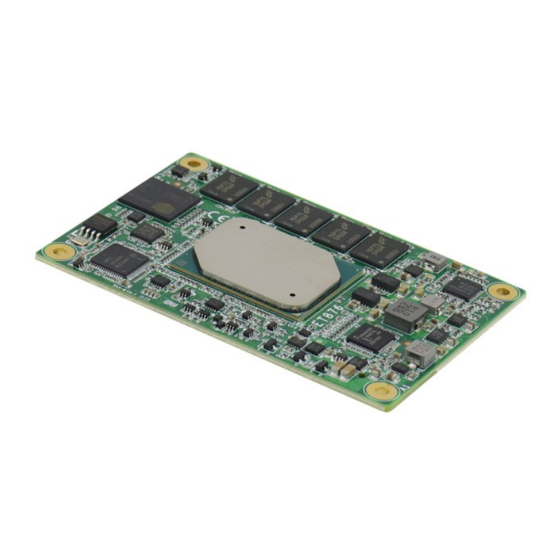
Product View Top View Bottom View Photos of ET876 *The photos above are for reference only. Some minor components may differ. Dimensions Unit: mm ET876 Series User’s Manual... -
Page 17: Chapter 2 Hardware Configuration
Hardware Configuration This section provides information on jumper settings and connectors on the ET876 in order to set up a workable system. On top of that, you will also need to install crucial pieces such as the CPU and the memory before using the product. The topics covered are: •... -
Page 18: Connector Location
Connector Location Board diagram of ET876 2.1.1 COMe Module Type 10 Connector (RECS1) B110 A110 Row A Row B Row A Row B Signal Signal Signal Signal GND (FIXED) GND (FIXED) RSVD RSVD GBE0_MDI3- GBE0_ACT# GPO2 GBE0_MDI3+ LPC_FRAME# PCIE_TX3+ PCIE_RX3+... - Page 19 B105 VCC_12V GND (FIXED) GND (FIXED) A106 VCC_12V B106 VCC_12V RSVD RSVD A107 VCC_12V B107 VCC_12V RSVD RSVD A108 VCC_12V B108 VCC_12V GPI0 GPO1 A109 VCC_12V B109 VCC_12V RSVD RSVD A110 GND (FIXED) B110 GND (FIXED) ET876 Series User’s Manual...
- Page 20 This page is intentionally left blank. ET876 Series User’s Manual...
-
Page 21: Chapter 3 Drivers Installation
Chapter 3 Drivers Installation This chapter introduces installation of the following drivers: • ® Intel Chipset Software Installation Utility • Graphics Driver • HD Audio Driver • ® Intel Trusted Execution Engine Drivers • ® Intel Serial I/O Drivers • LAN Driver... -
Page 22: Introduction
Follow the instructions below to complete the installation. Insert the disk enclosed in the package with the board. Click Intel on the left pane and then Intel(R) Apollolake Chipset Drivers on the right pane. Click Intel(R) Chipset Software Installation Utility. ET876 Series User’s Manual... - Page 23 Click Yes to accept the software license agreement and proceed with the installation process. On the Readme File Information screen, click Install for installation. When the driver is completely installed, restart the computer for changes to take effect. ET876 Series User’s Manual...
-
Page 24: Graphics Driver Installation
Read the Readme File Information and then click Next until the installation starts. Choose a destination folder for installation. When the driver is completely installed, click Finish and restart the computer for changes to take effect. ET876 Series User’s Manual... -
Page 25: Hd Audio Driver Installation
Click Realtek High Definition Audio Driver. On the Welcome screen of the InstallShield Wizard, click Next. Click Next until the installation starts. When the driver is completely installed, restart the computer for changes to take effect. ET876 Series User’s Manual... -
Page 26: Intel ® Trusted Execution Engine Drivers
Click Intel(R) TXE Drivers. When the Welcome screen appears, click Next. Accept the license agreement and click Next until the installation starts. As the driver has been sccessfully installed, restart the computer for changes to take effect. ET876 Series User’s Manual... -
Page 27: Intel ® Serial Io Drivers
When the Welcome screen to the InstallShield Wizard appears, click Next. Accept the license agreement and click Next. After reading the Readme File Information, click Next for installation. As the driver has been sccessfully installed, restart the computer for changes to take effect. ET876 Series User’s Manual... -
Page 28: Lan Driver Installation
LAN Driver Installation Click LAN Card on the left pane and then Intel LAN Controller Drivers on the right pane. Click Intel(R) I21x Gigabit Network Drivers.. When the Welcome screen appears, click Next. ET876 Series User’s Manual... - Page 29 On the Setup Options screen, tick the checkbox to select the desired driver(s) for installation. Then click Next to continue. The wizard is ready for installation. Click Install. As the installation is complete, restart the computer for changes to take effect. ET876 Series User’s Manual...
- Page 30 This page is intentionally left blank. ET876 Series User’s Manual...
-
Page 31: Chapter 4 Bios Setup
Chapter 4 BIOS Setup This chapter describes the different settings available in the AMI BIOS that comes with the board. The topics covered in this chapter are as follows: • Main Settings • Advanced Settings • Chipset Settings • Security Settings •... -
Page 32: Introduction
These defaults have been carefully chosen by both AMI and your system manufacturer to provide the absolute maximum performance and reliability. Changing the defaults could make the system unstable and crash in some cases. ET876 Series User’s Manual... -
Page 33: Main Settings
ET876-X7LV8G. Main Settings BIOS Setting Description System Date Sets the date. Use the <Tab> key to switch between the data elements. System Time Set the time. Use the <Tab> key to switch between the data elements. ET876 Series User’s Manual... -
Page 34: Advanced Settings
Displays CPU configuration parameters. USB Configuration Displays USB configuration parameters. Network Stack Netowrk Stack settings. Configuration CSM Configuration Enables / Disables option ROM execution settings, etc. [1]: DP to LVDS Configuration is available for ET876-X7LV8G and ET876-420LVM8G. ET876 Series User’s Manual... - Page 35 EFI protocol and INTIA interface will not be available. Pending operation Schedule an operation for the security device. Note: Your computer will reboot during restart in order to change state of security device. Options: None, TPM Clear ET876 Series User’s Manual...
- Page 36 4.4.2 ACPI Settings Setting Description ACPI Sleep Selects an ACPI sleep state (Suspend Disabled or S3) State where the system will enter when the Suspend button is pressed. ET876 Series User’s Manual...
- Page 37 BIOS Setup 4.4.3 DP to LVDS Configuration Note: DP to LVDS Configuration is only available for ET876-X7LV8G & ET876-420LVM8G. BIOS Setting Description LVDS Support Enables / Disables eDP to LVDS. are the settings when LVDS Support is enabled. Below ET876 Series User’s Manual...
- Page 38 ET876 Series User’s Manual...
- Page 39 BIOS Setup ET876 Series User’s Manual...
- Page 40 F81964 Super IO Configuration BIOS Setting Description Serial Port 1 Configuration Set parameters of Serial Port 1 (COMA). Serial Port 2 Configuration Set parameters of Serial Port 1 (COMB). 4.4.4.1. Serial Port 1 Configuration 4.4.4.2. Serial Port 2 Configuration ET876 Series User’s Manual...
- Page 41 BIOS Setup 4.4.5 F81804SEC Super IO Configuration BIOS Setting Description Serial Port 1 Configuration Set parameters of Serial Port 1 (COMA). Serial Port 2 Configuration Set parameters of Serial Port 2 (COMB). 4.4.5.1. Serial Port 1 Configuration ET876 Series User’s Manual...
- Page 42 4.4.5.2. Serial Port 2 Configuration ET876 Series User’s Manual...
- Page 43 Options: Always on, Always off Temperatures / These fields are the parameters of the hardware Voltages monitoring function feature of the motherboard. The values are read-only values as monitored by the system and show the PC health status. ET876 Series User’s Manual...
- Page 44 Enables / Disables the number of cores to enable Cores in each processor package. Monitor Mwait Enables / Disables Monitor Mwait. 4.4.8.1. Socket 0 CPU Information 4.4.8.2. CPU Power Management 4.4.8.3. Active Processor Core 4.4.8.4. Monitor Mwait ET876 Series User’s Manual...
- Page 45 Maximum time the device will take before it delay properly reports itself to the Host Controller. “Auto” uses default value: for a root port it is 100 ms, for a hub port, the delay is taken from hub descriptor. ET876 Series User’s Manual...
- Page 46 4.4.9 Network Stack Configuration BIOS Setting Description Network Stack Enables / Disables UEFI network stack. ET876 Series User’s Manual...
- Page 47 Option ROM. • Immediate executes the trap right away • Postponed executes the trap during legacy boot. Boot option filter Controls the priority of Legacy and UEFI. Network Controls the execution of UEFI and Legacy PXE OpROM. ET876 Series User’s Manual...
-
Page 48: Chipset Settings
Chipset Settings ET876 Series User’s Manual... - Page 49 Description ASPM PCI Express Active State Power Management Settings. L1 Substates PCI Express L1 Substates Settings. PME SCI Enables / Disables PCI Express PME SCI. PCIe Speed Configures the PCIe speed as Auto, Gen1, or Gen2. ET876 Series User’s Manual...
- Page 50 SATA ports (up to 3Gb/s supported per port). 4.5.3 SCC Configuration BIOS Setting Description SCC eMMC Support Enables / Disables SCC eMMC support. eMMC Max Speed Select the eMMC max. speed. Options: HS400, HS200, DDR50 ET876 Series User’s Manual...
- Page 51 Enables / Disables XDCI. Options: Disable, PCI Mode XHCI Disable Options to disable XHCI Link Compliance Mode. Compliance Mode Default is FALSE to not disable Compliance Mode. Set True to disable Compliance Mode. Options: False, True ET876 Series User’s Manual...
-
Page 52: Security Settings
Security Settings BIOS Setting Description Administrator Sets an administrator password for the setup Password utility. User Password Sets a user password. Secure Boot Customizable secure boot settings. ET876 Series User’s Manual... - Page 53 Customization Secure Boot mode to STANDARD mode or CUSTOM mode, this change is effect after save. And after reset, the mode will return to STANDARD mode. Restore Factory Force System to User Mode. Configure NVRAM to ET876 Series User’s Manual...
- Page 54 Enroll Factory Defaults or load certificates from a file: Key Exchange Key 1.Public Key Certificate in: Authorized a)EFI_SIGNATURE_LIST Signature b)EFI_CERT_X509 (DER encoded) c)EFI_CERT_RSA2048 (bin) Forbidden Signature d)EFI_CERT_SHA256,384,512 Authorized 2.Authenticated UEFI Variable TimeStamps 3.EFI PE/COFF Image(SHA256) Key Source: OsRecovery Factory,External,Mixed Signatures ET876 Series User’s Manual...
-
Page 55: Boot Settings
New Boot Option Controls the placement of newly detected UEFI Policy boot options. Boot mode select Selects a Boot mode, Legacy / UEFI. Boot Option Priorities Sets the system boot order priorities for hard disk, CD/DVD, USB, Network. ET876 Series User’s Manual... -
Page 56: Save & Exit Settings
Restore Defaults Restores / Loads defaults values for all the setup options. Save as User Defaults Saves the changes done so far as User Defaults. Restore User Defaults Restores the user defaults to all the setup options. ET876 Series User’s Manual... -
Page 57: Appendix
Appendix This section provides the mapping addresses of peripheral devices and the sample code of watchdog timer configuration. -
Page 58: I/O Port Address Map
0x00000680-0x0000069F Motherboard resources 0x00000400-0x0000047F Motherboard resources 0x00000500-0x000005FE Motherboard resources 0x00000600-0x0000061F Motherboard resources 0x0000164E-0x0000164F Motherboard resources 0x0000F040-0x0000F05F Intel(R) Celeron(R)/Pentium(R) Processor SMBUS - 5AD4 0x0000D000-0x0000DFFF Intel(R) Celeron(R)/Pentium(R) Processor PCI Express Root Port - 5AD6 0x000003F8-0x000003FF Communications Port (COM1) ET876 Series User’s Manual... - Page 59 Programmable interrupt controller 0x000000B0-0x000000B1 Programmable interrupt controller 0x000000B4-0x000000B5 Programmable interrupt controller 0x000000B8-0x000000B9 Programmable interrupt controller 0x000000BC-0x000000BD Programmable interrupt controller 0x000004D0-0x000004D1 Programmable interrupt controller 0x0000F000-0x0000F03F Intel(R) HD Graphics 0x0000E000-0x0000EFFF Intel(R) Celeron(R)/Pentium(R) Processor PCI Express Root Port - 5ADB ET876 Series User’s Manual...
- Page 60 Address Device Description 0x0000F090-0x0000F097 Standard SATA AHCI Controller 0x0000F080-0x0000F083 Standard SATA AHCI Controller 0x0000F060-0x0000F07F Standard SATA AHCI Controller 0x00000040-0x00000043 System timer 0x00000050-0x00000053 System timer ET876 Series User’s Manual...
-
Page 61: Interrupt Request Lines (Irq)
Intel(R) I210 Gigabit Network Connection #2 IRQ 4294967284 Intel(R) I210 Gigabit Network Connection #2 IRQ 4294967283 Intel(R) I210 Gigabit Network Connection #2 IRQ 4294967282 Intel(R) I210 Gigabit Network Connection #2 IRQ 4294967280 Intel(R) Trusted Execution Engine Interface ET876 Series User’s Manual... - Page 62 Intel(R) Serial IO GPIO Host Controller - INT3452 IRQ 14 Intel(R) Serial IO GPIO Host Controller - INT3452 IRQ 14 Intel(R) Serial IO GPIO Host Controller - INT3452 IRQ 4294967294 Standard SATA AHCI Controller IRQ 0 System timer ET876 Series User’s Manual...
-
Page 63: Watchdog Timer Configuration
**endptr; char SIO; printf("Fintek 81804 watch dog program\n"); SIO = Init_F81804(); if (SIO == 0) printf("Can not detect Fintek 81804, program abort.\n"); return(1); }//if (SIO == 0) if (argc != 2) printf(" Parameter incorrect!!\n"); return (1); ET876 Series User’s Manual... - Page 64 DisableWDT(void) unsigned char bBuf; Set_F81804_LD(0x07); //switch to logic device 7 bBuf = Get_F81804_Reg(0xFA); bBuf &= ~0x01; Set_F81804_Reg(0xFA, bBuf); //disable WDTO output bBuf = Get_F81804_Reg(0xF5); bBuf &= ~0x20; bBuf |= 0x40; Set_F81804_Reg(0xF5, bBuf); //disable WDT //--------------------------------------------------------------------------- //--------------------------------------------------------------------------- ET876 Series User’s Manual...
- Page 65 Init_Finish; F81804_BASE = 0x00; result = F81804_BASE; Init_Finish: return (result); //--------------------------------------------------------------------------- void Unlock_F81804 (void) outportb(F81804_INDEX_PORT, F81804_UNLOCK); outportb(F81804_INDEX_PORT, F81804_UNLOCK); //--------------------------------------------------------------------------- void Lock_F81804 (void) outportb(F81804_INDEX_PORT, F81804_LOCK); //--------------------------------------------------------------------------- void Set_F81804_LD( unsigned char LD) Unlock_F81804(); outportb(F81804_INDEX_PORT, F81804_REG_LD); outportb(F81804_DATA_PORT, LD); Lock_F81804(); ET876 Series User’s Manual...
- Page 66 F81804_DATA_PORT (F81804_BASE+1) //--------------------------------------------------------------------------- #define F81804_REG_LD 0x07 //--------------------------------------------------------------------------- #define F81804_UNLOCK 0x87 #define F81804_LOCK 0xAA //--------------------------------------------------------------------------- unsigned int Init_F81804(void); void Set_F81804_LD( unsigned char); void Set_F81804_Reg( unsigned char, unsigned char); unsigned char Get_F81804_Reg( unsigned char); //--------------------------------------------------------------------------- #endif // F81804_H ET876 Series User’s Manual...
- Page 67 Our company network supports you worldwide with offices in Germany, Austria, Switzerland, the UK and the USA. For more information please contact: Headquarters Germany FORTEC Elektronik AG Augsburger Str. 2b 82110 Germering Phone: +49 89 894450-0 E-Mail: info@fortecag.de Internet: www.fortecag.de Fortec Group Members Austria Distec GmbH Office Vienna...
Need help?
Do you have a question about the ET876 and is the answer not in the manual?
Questions and answers