
Summary of Contents for Idview Digital E-P132-X
- Page 1 SERIAL TO ETHERNET CONVERTER E-P132-X User Manual http://www.tcpipweb.com.tw HIMAQ S.R.L - Tel.: (011) 4709-3505 - Mail: himaq@himaq.com.ar - WEB: http://www.himaq.com.ar...
-
Page 2: Table Of Contents
Table of Contents Introduction …………………...………………………………………………4 Overview …………………………………………………………………………... 5 Package Checklist …………………………………………………………………. 6 Block Diagram …………………………………………………………………….. 7 Product Features …………………………………………………………………. 8 Product Specifications ……………………………………………………………. 9 Converter Description & Installation ………………………………… 11 Product Panel Views ……………………………………………………………… 11 Left Side …………………………………………………………………………… 12 Right Side ………………………………………………………………………….. 13 LED Indicators ……………………………………………………………………. - Page 3 Initial IP Configuration …………………………………………………………... 18 Device Management Utility of ETM ……………………………………………... 19 Menu “View” ……………………………………………………………………… 20 Menu “Config” ……………………………………………………………………. 20 Web Console Configuration ……………………………………………………… 22 Controller Status ………………………………………………………………….. 23 Controller Setup …………………………………………………………………... 25 Controller Updated ……………………………………………………………….. 31 Factory Default Setting …………………………………………………………… 32 Self-Testing …………………………………………………………………….
-
Page 4: Introduction
We are providing new ways of connecting serial devices to a Local Area Network (LAN) or Wide Area Network (WAN). E-P132-X TCP/IP converter is designed to operate serial ports over 10/100M Ethernet networks. The data is transmitted via TCP/IP protocol. -
Page 5: Overview
Overview E-P132-X TCP/IP converter is designed to make your serial devices Internet ready instantly. ARM-7 Series of E-P132-X TCP/IP converter makes them the ideal choice for connecting your RS-232 or RS-422/485 serial devices—such as PLCs, meters, and sensors to an IP-based Ethernet LAN, making it possible for your software to access serial devices anywhere and anytime over a local LAN or the Internet. -
Page 6: Package Checklist
Package Checklist ARM-7 product is shipped with the following items: 1 unit of E-P132-X TCP/IP converter 1 unit of Power Adaptor (9V~12V DC, 500mA) Documentation & Software CD NOTE: Notify your sales representative if any of the above items is missing or damaged. -
Page 7: Block Diagram
Block Diagram Low-cost devices usually are equipped with low speed processors and limited memories. In reality, they are neither having the capability nor practicality to manage complicated network TCP/IP protocols. ARM-7 Series is a low cost while providing high performance network solution by converting data stream between network TCP/IP and popular serial port signals. -
Page 8: Product Features
Product Features □ □ Data Conversion between RS-232/422/485 and Ethernet □ Convert serial device (RS-232, RS-422, RS-485) data/signal into the TCP/IP package data/signal and send them out with the Ethernet DataStream; or convert the TCP/IP package data/signal into serial device data/signal. □... -
Page 9: Product Specifications
Product Specifications CPU : 32-bits ARM-7 CPU , 25 MHz RAM : 2 M Bytes SDRAM ( 1 M * 16Bits ) ROM : 128 K Bytes Flash ROM Ethernet Port Type : RJ-45 Connector Speed : 10 /100 M bps ( Auto Detecting ) Protocol : ARP , IP , ICMP , UDP , TCP , HTTP , DHCP Protocol (Optional):PPPoE , PPPoM Mode : TCP Server / TCP Client / UDP... - Page 10 Serial Port Port : RS-232 * 1 Port ,RS-422/RS-485 * 1 Port Speed:300 bps~230.4 K bps Parity:None , Odd , Even , Mark , Space Data Bit:5 , 6 , 7 , 8 Stop Bit : 1 , 2 RS-232 Pins : Rx , Tx , GND , RTS , CTS , DTR , DSR , DCD RS-422 : Rx+ , Rx- , Tx+ , Tx- (Surge Protect) RS-485 : Data+ , Data- (Surge Protect) Built –in RS-422/RS-485 Terminal Resistor...
-
Page 11: Converter Description & Installation
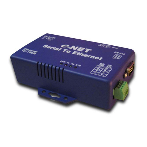
Converter Description Product Panel View RS-422 / 485 Terminator Reset Button DC-In Power Outlet Serial Port RS-232 Serial Port RS-485/RS-422 LED Indicators HIMAQ S.R.L - Tel.: (011) 4709-3505 - Mail: himaq@himaq.com.ar - WEB: http://www.himaq.com.ar... -
Page 12: Left Side
Connect the power line to the power outlet at the left side of E-P132-X TCP/IP converter and put the adapter into the socket. the power is properly supplied, the “SYS” red color LED will be blink each time in one second. -
Page 13: Right Side
Right Side RS-232 RS-422 / 485 Serial Port of RS-232/RS-422/RS-485 Connect the serial data cable between the converter and the serial device. Follow the setup procedure to configure the parameters of the converter. (see the following chapters ). HIMAQ S.R.L - Tel.: (011) 4709-3505 - Mail: himaq@himaq.com.ar - WEB: http://www.himaq.com.ar... -
Page 14: Led Indicators
LED Indicators SYS “Red LED”: Power indicated (when the power is on the LED will flash each time in one second ) Rx “Green LED”: Network signal receiving indicated (when receive any signal form network the LED will flash) Tx “Red LED”: Network signal transforming indicated (when transmit any signal to network the LED will flash) LAN “LED”: On-line indicated (when converter link to LAN then the LED will keep on)100M- Green LED、10M- Red LED... -
Page 15: Terminator & Reset Button
Terminator & Reset button Reset Button Terminator Resent Button Press the button then turn on the power and waiting for 3 seconds. Converter will reset to factory default. Terminator There is terminator resistor built in. If the switch 1 & 2 are set in “ON” position , 120 Ohm resistor is connected between the signals. -
Page 16: Wiring Architecture
Wiring Architecture RS-232 Wiring Architecture HIMAQ S.R.L - Tel.: (011) 4709-3505 - Mail: himaq@himaq.com.ar - WEB: http://www.himaq.com.ar... - Page 17 RS-422 / RS-485 Wiring Architecture When you finish the steps mentioned above and the LED indicators are as shown, the converter is installed correctly. You can use the Setup Tool “ETM.exe” to setup the IP Address. To proceed the advanced parameters setup, please use a web browser (IE or Netscape) to continue the detailed settings.
-
Page 18: Converter Configuration
Converter Configuration Initial IP Configuration When setting up your converter for the first time, the first thing you should do configure the IP address. This chapter introduces the method to configure the device server’s IP address. For more details about network settings, see “Web Console Configuration”. -
Page 19: Device Management Utility Of Etm
Device Management Utility On PC we provide a Device Management Utility named ETM.exe which is an executable program in Windows 32 bit environments. ETM Setup Tool is used to detect and setup the installed converters. It uses UDP broadcast packets to query and configure converters on the network. -
Page 20: Menu "View
Menu “View” □ □ View -> Refresh F5 □ Refresh the status. ETM will send another query to get updated information. (see Figure 3.2). Note: Always run the “View-> Refresh” after any data change. (Figure 3.2) ( Figure 3.2 ) View ->... - Page 21 Press ENTER or select [IP Address] in the [Config] menu, a dialog will be shown (see Figure 3.4). Note : Because ETM uses broadcast UDP packets, for the sake of security, it allows configuration only when device's setup password is empty. (Figure 3.4) ( Figure 3.4 ) Assign an IP Address with the same Subnet Mask of your computer, avoiding any...
-
Page 22: Web Console Configuration
Web Console Configuration In addition to basic IP address and subnet mask, specific device settings can be set through HTTP protocol with popular browsers, e.g. Internet Explorer, Netscape, etc. Setup of the converter is as easy as surfing on WWW, no special software will be required. -
Page 23: Controller Status
Controller Status The Login Page Setup of E-P132-X TCP/IP converter is as easy as surfing on WWW, no special software will be required. Popular Browsers, such as IE or Netscape, can easily do the setup process. In the browser URL field, set the IP address of device directly, To enter the “Controller Status”... - Page 24 The password will be reset to the factory default as “empty”. E-P132-X TCP/IP converter uses the same password protection mechanism commonly used in Windows NT or UNIX. If there are more than “3 consecutive failures”...
-
Page 25: Controller Setup
Controller Setup □ □ The Setup Page □ Type the correct password in the “Password” field and click the [Login] button in the “Controller Status” page, then the “Controller Setup” page will appear (see Figure 3.7). Note: If you forget the password or can’t login successfully, please contact the manufacturer directly. - Page 26 □ □ IP Address □ The IP address of E-P132-X TCP/IP converter, 4 digits separated by Don’t let it conflict with the other devices on the network. If DHCP client mode is enabled and there's a DHCP server on the network, this field will be assigned by DHCP server automatically.
- Page 27 □ □ Network link speed □ Ethernet physical link speed. “Auto” means the speed is automatically selected by the converter. You can also specify “10Mbps” or “100Mbps” to match the speed of the HUB. □ □ DHCP client □ DHCP client mode could be enabled/disabled statues. If DHCP is enabled, there should be a DHCP server on the network.
- Page 28 □ □ Report device ID when connected □ In TCP mode, if this parameter is enabled, every time when the socket is connected, E-P132-X TCP/IP converter will immediately report its device ID in the following formats: Serial #1 nnnnnA[LF][CR] Serial #2...
- Page 29 □ □ Socket port □ □ □ Port number □ A socket port assigned for the serial port. It’s a 16-bit number , ranging from 1 to 65535. Because the numbers below 1000 are used for specific purposes (e.g. 80 is for HTTP protocol), we suggest you use the numbers larger than 1000.
- Page 30 A socket port assigned for the serial port. It’s a 16-bit number , ranging from 1 to 65535. Because the numbers below 1000 are used for specific purposes (e.g. 80 is for HTTP protocol), we suggest you use the numbers larger than 1000. Generally the port number 4660 is used for the serial communication.
-
Page 31: Controller Updated
Controller Updated Press “Update” Button After you finish the detailed parameter setting. The converter will save all parameters into internal non-volatile memory and then reboot (see Figure 3.8). It takes about 5 seconds to complete the whole process, and a new login page will be presented (see Figure 3.1). (Figure 3..8) You can re-login and check if all parameters have been correctly saved. -
Page 32: Factory Default Setting
Factory Default Setting If by chance, you forget the setup password, or have incorrect settings making the converter inoperable, there are two ways to reset the setting and the following procedures can be used to reset all settings to factory default: 1. -
Page 33: Self-Testing
Self-Testing After completing the wiring and parameter setting, we should verify if the setting is correct or not. This chapter will introduce how to use a single computer to test if the converter behaves well. The operating system can be Windows 95, 98, ME, XP, 2000. The “Hyper Terminal”... -
Page 34: Hyper Terminal For Tcp/Ip Winsock
Hyper Terminal for TCP/IP WinSock Initiate a Hyper Terminal from the Start Menu in Windows (see Figure 4.1), give a terminal name, choose an icon, and press “OK” button (see Figure 4.2). (Figure 4.1) (Figure 4.2) HIMAQ S.R.L - Tel.: (011) 4709-3505 - Mail: himaq@himaq.com.ar - WEB: http://www.himaq.com.ar... - Page 35 Select “TCP/IP(Winsock)” option at the “Connect using:” field (see Figure 4.3) (Figure 4.3) After “OK” button is pressed, Figure 4.4 appears. Enter the converter’s IP address (e.g. 192.168.0.10) at the “Host address:” field, and the Socket port number set for the Serial Port 1 at the “Port number:”...
- Page 36 After “OK” button is pressed, Figure 4.5 appears. If the Hyper Terminal connects with the converter successfully, the time clock at the “left lower” corner “Connected hh:mm:ss” will start counting. (Figure 4.5) HIMAQ S.R.L - Tel.: (011) 4709-3505 - Mail: himaq@himaq.com.ar - WEB: http://www.himaq.com.ar...
-
Page 37: Hyper Terminal For Com Port
Hyper Terminal for COM Port Initiate another Hyper Terminal as a COM Port Terminal (in Figure 4.3, select COM 1 or other COM port instead of “TCP/IP (Winsock)”). Set the COM port Properties to be the same as those set for the Serial Port of the converter ( 9600.N.8.1 ). (Figure 4.3) Data Transmission When all steps described above are finished, type any characters on the COM Port... -
Page 38: Appendix A - Faq
Q. Why can’t the ETM.exe detect the converter on the network? A. Please check . if the power is properly plugged to the converter. ( Please refer “SYS’ LED ) . if the network cable is properly connected between the converter and the Hub. ( Please refer LAN LED ) Q. -
Page 39: Appendix B - Pin Outs And Cable Wiring
Pin outs and Cable Wiring □ □ DC Power outlet □ □ □ RJ-45 Pin Assignment □ □ □ RS-232 Pin Assignment □ The pin assignment scheme for a 9-pin male connector on a DTE is given below. PIN 1 : DCD PIN 2 : RXD PIN 3 : TXD PIN 4 : DTR...
Need help?
Do you have a question about the E-P132-X and is the answer not in the manual?
Questions and answers