Table of Contents
Advertisement
Quick Links
Advertisement
Table of Contents

Related Manuals for Lord MicroStrain WSDA-1500-SK


Summary of Contents for Lord MicroStrain WSDA-1500-SK
- Page 1 LORD USER MANUAL ® ® WSDA -1500-LXRS Wireless Sensor Data Aggregator...
- Page 2 LORD Sensing Systems 459 Hurricane Lane Suite 102 Williston, VT 05495 United States of America Phone: 802-862-6629 Fax: 802-863-4093 9:00 AM to 5:00 PM (Eastern Time US & Canada) http://www.microstrain.com sensing_support@LORD.com sensing_sales@LORD.com Document 8500-0048 Revision D Subject to change without notice.
-
Page 3: Table Of Contents
® ® WSDA -1500-LXRS User Manual Table of Contents Wireless Sensor Network Overview Gateway Overview 2.1 Gateway Components 2.2 Gateway Interface System Operation 3.1 Software Installation 3.2 System Connections 3.3 Gateway Operation 3.4 Gateway Communication 3.4.1 Gateway Configuration Sensor Node Access 4.1 Connect to Nodes 4.1.1 Add A Node Via Node Discovery 4.1.2 Add A Node Manually 4.1.3 Move Node To Base Station Frequency... - Page 4 ® ® WSDA -1500-LXRS User Manual 6.2.2 Navigating Graphs 6.2.3 Widgets Options 6.2.4 Time Series Widget Menu 6.2.5 Exporting Data Files Gateway Menu Navigation 7.1 Gateway Information 7.1.1 About the Gateway 7.1.2 Node List 7.2 Data Options Menu 7.2.1 CAN J1939 Output 7.2.2 Data Alias Definitions 7.2.3 SensorCloud™...
- Page 5 ® ® WSDA -1500-LXRS User Manual 10.2 Optimizing the Radio Link 10.2.1 Range Test 10.3 Multi-port Connector Interface Troubleshooting 11.1 Troubleshooting Guide 11.2 Communications Ports in Windows® Parts and Configurations 12.1 Standard Models 12.2 Wireless System Equipment Specifications 13.1 Physical Specification 13.2 Operating Specifications 13.3 Radio Specifications Safety Information...
-
Page 6: Wireless Sensor Network Overview
® ® WSDA -1500-LXRS User Manual Wireless Sensor Network Overview The LORD Sensing Wireless Sensor Network is a high- speed, scalable, sensor data acquisition and sensor networking system. Each system consists of wireless sensor interface nodes, a data collection gateway, and full- featured user software platforms based on the LORD Sensing Lossless Extended Range Synchronized (LXRS) data communications protocol. ... -
Page 7: Gateway Overview
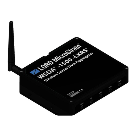
® ® WSDA -1500-LXRS User Manual Gateway Overview The WSDA-1500-LXRS is a network gateway designed to configure, co-ordinate, and collect sensor data from LORD Sensing wireless sensor nodes. The WSDA-1500-LXRS is Ethernet-capable and can be configured to operate with a static IP, a DHCP-enabled LAN, or as a datalogger to local memory. The WSDA-1500-LXRS is also capable of pushing sensor data onto a J1939-compatible CAN bus either by sending all of the sensor messages to one CAN address or by broadcasting user-selected messages onto the CAN bus. -
Page 8: Gateway Components
® ® WSDA -1500-LXRS User Manual 2.1 Gateway Components The WSDA - 1500- LXRS can be purchased individually or in a connectivity kit. The kit includes everything required to operate the WSDA - 1500- LXRS including a removable external antenna, a power supply, and cables for interfacing with the host computer or network. -
Page 9: Gateway Interface
® ® WSDA -1500-LXRS User Manual Gateway Interface The WSDA-1500-LXRS interfaces include a power input jack , a power on/off switch, an antenna connector for attaching the gateway antenna, an Ethernet jack, a multi-use (multi-port) connector, and a USB port reserved for future use. The indicators on the WSDA-1500-LXRS include a several device and data status indicators, and a power indicator. -
Page 10: System Operation
® ® WSDA -1500-LXRS User Manual System Operation The gateway is the interface between LORD Sensing sensor nodes and the data acquisition computer or network. The gateway co-ordinates the configuration and sampling of the nodes and can handle many nodes simultaneously. Communication between the nodes and gateway is wireless and uses the LORD Sensing LXRS and LXRS+ data communications protocols. -
Page 11: System Connections
® ® WSDA -1500-LXRS User Manual 3.2 System Connections To acquire sensor data the following components are needed: a LORD Sensing wireless sensor node, a LORD Sensing data gateway, and a host computer with access to the data acquisition software. The sensor, node, gateway, and software selection are application-dependent, but the basic interfaces are the same. -
Page 12: Gateway Operation
® ® WSDA -1500-LXRS User Manual 3.3 Gateway Operation NOTE The default configuration of Ethernet gateways is for DHCP network connectivity. To change the gateway communication settings, initial connection to a DHCP- enabled network is required. The Ethernet gateway has three primary operating sequences including gateway configuration, node configuration, and data acquisition, viewing and analysis. - Page 13 ® ® WSDA -1500-LXRS User Manual Figure 6 - Gateway Communication...
-
Page 14: Gateway Configuration
® ® WSDA -1500-LXRS User Manual 3.4.1 Gateway Configuration From the Devices window, highlight the base station and select the WSDA Control Panel tile. Figure 7 - Control Panel Access Log in to the gateway Control Panel with the default credentials: Login: wsda Password: wsda... - Page 15 ® ® WSDA -1500-LXRS User Manual A navigation panel on the left shows three menu categories: General, Data, and Tools. Figure 8 - Control Panel Menus a. General - This category includes menu selections for information about the gateway's iden- tity and time settings (About) and the sensor nodes it currently has data for in memory (Node List).
-
Page 16: Sensor Node Access
® ® WSDA -1500-LXRS User Manual Sensor Node Access 4.1 Connect to Nodes Several methods can be used in SensorConnect to establish communication with the nodes: the automatic node discovery feature, manually entering the node address, and scanning transmission frequency and node address ranges. 4.1.1 Add A Node Via Node Discovery For all LORD Sensing 200 Series nodes, a node discovery is triggered by turning on the node. - Page 17 ® ® WSDA -1500-LXRS User Manual If a red circle with a number appears next to the Base Station, the node is operating on a see Move Node To Base Station Frequency on page 20 separate radio channel ( Figure 10 - Node On Other Frequency...
-
Page 18: Add A Node Manually
® ® WSDA -1500-LXRS User Manual 4.1.2 Add A Node Manually Adding a node manually requires entering the node address and its current frequency setting. Figure 11 - Add Node By Address If the node was successfully added, two confirmation messages will appear and it will be listed under the Base Station. - Page 19 ® ® WSDA -1500-LXRS User Manual If the node failed to be added, a failure message will appear. This means the node did not respond to the base station which could indicate the node is not in idle mode or it may be on another frequency.
-
Page 20: Move Node To Base Station Frequency
® ® WSDA -1500-LXRS User Manual 4.1.3 Move Node To Base Station Frequency If a red circle with a number appears next to Base Station, the node is operating on a separate radio channel. Select the Base Station and then select the Nodes on Other Frequencies tile. -
Page 21: Configure Node
® ® WSDA -1500-LXRS User Manual Configure Node Node settings are stored to non-volatile memory and may be configured using SensorConnect. The configuration menus show the channels and configuration options available for the type of node being used. Figure 16 - Node Configuration 4.3 Sampling Configuration To start a sampling session, nodes can be selected individually by selecting the Node name >... - Page 22 ® ® WSDA -1500-LXRS User Manual Synchronized - By selecting Synchronized, all nodes in the network will periodically synchronize their time clocks to a beacon that is broadcasted by the WSDA gateway. Each beacon contains a UTC timestamp, allowing nodes to timestamp their collected data within an accuracy of +/- 50 Each node will also buffer data and transmit this data in time-slots allocated prior to sampling.
- Page 23 ® ® WSDA -1500-LXRS User Manual Log/Transmit: Select "Log Only" to have the node store all collected data to flash memory for later download. Select "Transmit Only" to have the node transmit all data while it is collected. Or select "Log and Transmit" to have the node perform both operations. % Total: Indicates the percentage of total over-the-air bandwidth reserved for each node.
-
Page 24: Gateway Settings
® ® WSDA -1500-LXRS User Manual Gateway Settings 5.1 Transmit Power The transmit power level may require adjustment if power consumption is a concern or in regions where there are transmit power restrictions. Lowering the power output reduces power consumption, but it also reduces the wireless communication range between the gateways and nodes. -
Page 25: Change Frequency
® ® WSDA -1500-LXRS User Manual Change Frequency There are 14 available frequency channels between 2.405 and 2.470 GHz. Wireless nodes and the gateway must be on the same frequency channel to communicate. NOTE The gateway can automatically manage nodes operating on different frequencies by using the Node Discovery feature in SensorConnect. -
Page 26: Set Nodes To Idle
® ® WSDA -1500-LXRS User Manual NOTE Setting the transmit frequency using SensorConnect is temporary for Ethernet gateways and will revert back to the frequency setting selected in the gateway Control Panel when the gateway is powered off or rebooted ( see Gateway Configuration on page 14 for how to change the frequency setting in Control Panel) -
Page 27: Viewing Data
® ® WSDA -1500-LXRS User Manual Viewing Data 6.1 SensorCloud Data acquired through SensorConnect is automatically saved on the host computer. Saved data can be uploaded to SensorCloud. Ethernet gateways provide the option to automatically port the data to SensorCloud during data acquisition for near real-time display and aggregation. Ethernet gateways can also be configured to save data locally to internal memory for future upload to the host computer or SensorCloud. - Page 28 ® ® WSDA -1500-LXRS User Manual Figure 22 - SensorCloud Menu Views Device - The device list shows every Ethernet gateway and API device associated with the SensorCloud account, including owned, shared, and demo devices. This view provides links to each device’s SensorCloud subscription plan, configuration options, and a summary of last communications and data transactions.
- Page 29 ® ® WSDA -1500-LXRS User Manual Figure 23 - SensorCloud Data View ® Figure 24 - MathEngine View...
-
Page 30: Sensorconnect
® ® WSDA -1500-LXRS User Manual Figure 25 - FFT Graph in SensorCloud For more information about SensorCloud features and navigation, refer to the SensorCloud website:http://www.sensorcloud.com/, or contact LORD Sensing Technical Support. 6.2 SensorConnect 6.2.1 Using Dashboards and Widgets Collected data is viewed on the Data page through the creation of dashboards and widgets. Think of dashboards as individual pages and widgets as an illustration on the page. -
Page 31: Navigating Graphs
® ® WSDA -1500-LXRS User Manual 6.2.2 Navigating Graphs Use the mouse along with the shift and control keys inside the graph window to adjust the data view. Control Action Mouse wheel Zoom in/out on x-axis Shift + mouse wheel Zoom in/out on y-axis Mouse double-click Zoom to extends... -
Page 32: Time Series Widget Menu
® ® WSDA -1500-LXRS User Manual 6.2.4 Time Series Widget Menu The Time Series Widget menu has two features to help optimize sensor data collection for export to a .csv file. Snap to Latest captures the most recent data and Zoom isolates specific events from a see Exporting Data Files on page 32 larger data sample ( Figure 28 - Time Series Widget Menu... -
Page 33: Gateway Menu Navigation
® ® WSDA -1500-LXRS User Manual Gateway Menu Navigation 7.1 Gateway Information The General category provides information about the gateway identity, the wireless nodes it serves, and its current time settings. These are informational only, and no user adjustments may be made in these menus. - Page 34 ® ® WSDA -1500-LXRS User Manual Serial Number: an alpha-numeric identifier embedded in the WSDA-1500-LXRS hardware. The serial number is assigned when the gateway is manufactured. MAC Address: an alpha-numeric identifier embedded in the network card of the WSDA-1500- LXRS hardware. A MAC (Media Access Control) Address is a unique identifier assigned to all Ethernet devices to manage communications on the network.
-
Page 35: Node List
® ® WSDA -1500-LXRS User Manual System Up-time: the elapsed time since the gateway was last powered on and booted up. The system up-time will be zeroed when the gateway power is cycled or it is rebooted from the Tools > Reboot menu. -
Page 36: Data Options Menu
® ® WSDA -1500-LXRS User Manual 7.2 Data Options Menu The Data category provides data handling options such as selecting which data is sent to the CAN J1939 bus, uploaded to SensorCloud™, and downloaded to a host computer. Data can also be cleared from the WSDA-1500-LXRS internal memory. -
Page 37: Can J1939 Output
® ® WSDA -1500-LXRS User Manual 7.2.1 CAN J1939 Output In addition to saving locally or uploading through an Ethernet connection, data acquired from sensor nodes can also be pushed onto a CAN J1939 bus for reactive command and control of external devices and other applications. - Page 38 ® ® WSDA -1500-LXRS User Manual NOTE The wireless data transmit rate (between the node and the gateway) directly impacts the data bandwidth on the CAN bus. If the aggregate transmit rate of the wireless network (combined bandwidth use of active nodes) is high enough and there are other devices (besides the gateway) on the CAN bus, the bus may be overwhelmed, resulting in lost data.
- Page 39 ® ® WSDA -1500-LXRS User Manual With either setting, the gateway will be identified by the name assigned to it when manufactured (which is displayed to the right of the Source selection menu). This name provides the host CAN bus with information about the device that determines its data priority relative to other devices on the Table 7 - WSDA-1500-LXRS J1939 Values bus ( Description...
- Page 40 ® ® WSDA -1500-LXRS User Manual allowed (0xFF00 through 0xFFFF). Additionally, the user must also define which data values the WSDA should forward onto the bus for each given PGN and under which conditions. To define which data to send for a given PGN, the user must specify the address of the wireless node producing the data and the name of each data stream from that node which should be forwarded onto the bus.
- Page 41 ® ® WSDA -1500-LXRS User Manual To enter the broadcast messages in the J1939 menu, type in the appropriate field. When the PGN field is selected, the Payload field will appear. If all values for the message are to be included, leave the Ch.
- Page 42 ® ® WSDA -1500-LXRS User Manual Once created, save the text file and then upload it to the gateway by clicking the Browse for File button in the J1939 menu. Navigate to the file, click OK, and then click the Submit button to save the configuration ( Figure 35 - Upload Configuration File Figure 35 - Upload Configuration File...
- Page 43 ® ® WSDA -1500-LXRS User Manual Host Bus Integration Destination Specific Messages: With this message format, data packets received from the sensor nodes will be passed onto the J1939 CAN bus as received. An integrity check is made before sending the packet over the bus, but no other process is applied before wrapping the data in the J1939 protocol.
-
Page 44: Data Alias Definitions
® ® WSDA -1500-LXRS User Manual 7.2.2 Data Alias Definitions The names of data the sensor network produces and the WSDA can push onto the CAN bus are defined below. All data is in big-endian format unless otherwise noted. Some data channels have fixed sizes or depend on the node settings. - Page 45 ® ® WSDA -1500-LXRS User Manual Value Definition Applicable Packet Syncrhonized Sampling (v1,v2),Derived Syn- crhonized Sampling (v1), Asynchronous (v1), noderssi RSSI value of node Asynchronous Digital and Analog (v1), Structural Health (v2), Diagnostic (V1) Table 9 - Data Channel Definitions The following table summarizes the Diagnostic Channel definitions.
-
Page 46: Sensorcloud™ Upload Filter
® ® WSDA -1500-LXRS User Manual 7.2.3 SensorCloud™ Upload Filter By default, the WSDA - 1500- LXRS uploads all sensor data stored in the gateway memory to SensorCloud™. The Upload Filter function allows the user to select the data to be uploaded. Figure 36 - Data Upload Filter The Upload Filter menu describes how to set up a filter. -
Page 47: Wsda Data Downloader Calibration Coefficients
® ® WSDA -1500-LXRS User Manual 7.2.4 WSDA Data Downloader Calibration Coefficients The Calibration feature allows the user to specify coefficients for converting between engineering units with a linear relationship, and to correct for sensor biases in sensor data saved in the gateway memory. - Page 48 ® ® WSDA -1500-LXRS User Manual The calibration conversion formula assumes a linear relationship between the original units (such as A/D bits) and new engineering units (such as ), and it is expressed mathematically as y=mx+b , where y is the engineering units at a given point (measurement), m is the slope of the line that represents the linear ratio, x is the original unit value at a given point, and b is a unit conversion offset (in the case of unit conversions) or the fixed zero load offset of the sensor (in the case of measurement calibration coefficients).
-
Page 49: Clear Stored Data
® ® WSDA -1500-LXRS User Manual 7.2.5 Clear Stored Data The Clear Data feature is used to erase all sensor node data from the gateway's internal memory. Before erasing, the user should confirm that all data has been transmitted to SensorCloud™. The Current Data Size display indicates the amount of data currently stored in the memory. -
Page 50: Diagnostics
® ® WSDA -1500-LXRS User Manual 7.3.1 Diagnostics The diagnostics feature is used to troubleshoot the WSDA-1500-LXRS. The diagnostics window displays a report from the gateway internal log file. The log records the diagnostic checks from three possible sources of error: the timing engine, SensorCloud™ data upload, and the data logger. These diagnostic checks are performed once at every power up and then periodically as the gateway is in on. -
Page 51: Configuration
® ® WSDA -1500-LXRS User Manual 7.3.2 Configuration The Configuration menu allows the user to set parameters associated with WSDA-1500-LXRS operation. The settings include configuring the communication settings, enabling and disabling operating sequences, changing the node synchronization beacon state, and changing the gateway wireless node communication frequency. - Page 52 ® ® WSDA -1500-LXRS User Manual page 54 ), sets the node synchronization beacon, sets the gateway wireless node communication frequency, and then begins logging data. WSN Beacon: The beacon is used to precisely coordinate node data acquisition and data see Using the transmission in the wireless sensor network (WSN) during synchronized sampling ( Beacon on page 62 WSN Channel: The channel setting refers to the wireless sensor network (WSN) transmission...
- Page 53 ® ® WSDA -1500-LXRS User Manual is 192.168.0.100, and the subnet mask is 255.255.255.0 the gateway can communicate with all addresses between 192.168.0.0 and 192.168.0.255. The Static Gateway option allows users to define an address the gateway can communicate with outside of its subnet. This requires the gateway to be able to access the internet on a static network.
-
Page 54: Time Options
® ® WSDA -1500-LXRS User Manual allows remote access to the gateway Control Panel through Live Connect ( see Remote Connectivity on page 59 ). When enabled the gateway will upload newly received data to SensorCloud™ at two minute intervals. In other words, it will transmit new data, wait two minutes, and then transmit any additional new data. - Page 55 ® ® WSDA -1500-LXRS User Manual The WSDA-1500-LXRS can synchronize its system time from four different time sources: Network Time Protocol (NTP) time servers, manual user entry, the last known time reference, or from an attached device with GPS. Time servers allows the WSDA-1500-LXRS to synchronize with external servers that provide the NTP service.
-
Page 56: Reboot
® ® WSDA -1500-LXRS User Manual To insert a new time server, fill in the last line Order column with the numerical order to place the time server in the list. Next enter the host name of the time server in the Hostname column. Click the Insert button. -
Page 57: Operating System (Os) Upgrade
® ® WSDA -1500-LXRS User Manual 7.3.5 Operating System (OS) Upgrade Periodically, new versions of the WSDA - 1500- LXRS operating system will be released to add features or make other updates to the system. On the recommendation of LORD Sensing Technical Support, gateways can be upgraded to the latest available operating system to take advantage of these new features or to correct operating issues. Updates may be found on the LORD Sensing website (... -
Page 58: Change Password
® ® WSDA -1500-LXRS User Manual 7.3.6 Change Password The Change Password feature is used to change the username and the password required at log-in to the WSDA-1500-LXRS Control Panel. The default username and password are: a. Login: wsda b. Password: wsda Enter the current username and password and then the new password twice and select Submit. -
Page 59: Remote Connectivity
® ® WSDA -1500-LXRS User Manual Remote Connectivity Some SensorCloud™ data plans allow remote access to the WSDA - 1500- LXRS through the SensorCloud™ web interface. This allows access to the gateway Control Panel (including data downloading) and to Live Connect and SensorConnect for remote configuration of gateways and nodes. Data downloading from the gateway memory is also available in this way. - Page 60 ® ® WSDA -1500-LXRS User Manual Download Data Remotely 1. Download the WSDA Data Downloader from the WSDA-1500-LXRS product page at: http://www.microstrain.com/wireless/WSDA-1500 >Downloads > Software. 2. Connect to the gateway Control Panel as described above. 3. Copy the URL from the browser address bar when in Control Panel ( Figure 46 - Control Panel URL 4.
- Page 61 ® ® WSDA -1500-LXRS User Manual Figure 47 - Device Live Connect Access 2. When the button is selected a file download (info.live_connect) will begin. Open the file when the download is complete, and Live Connect will open automatically. The device will Figure 48 - Remote Live appear in the Live Connect window under User Defined WSDA's ( Connect Connection...
-
Page 62: Using The Beacon
® ® WSDA -1500-LXRS User Manual Using the Beacon In synchronized sampling, the beacon feature is used to coordinate sampling and transmission timing between multiple nodes. The primary purpose is to avoid data collision, guarantee timing between samples from different nodes, and to time-stamp the data. The beacon cannot be used in any another sampling mode. -
Page 63: System Bandwidth In Synchronized Sampling
® ® WSDA -1500-LXRS User Manual 9.1 System Bandwidth in Synchronized Sampling When using synchronized sampling all nodes in the wireless network are queried and given time slots of various lengths based on their configuration (# of channels, sample rate, etc.). Nodes will only transmit data during these time slots, therefore eliminating over-the-air data collisions. -
Page 64: Gateway Installation
® ® WSDA -1500-LXRS User Manual Gateway Installation 10.1 Installation Recommendations The WSDA-1500-LXRS is rated for indoor use only, unless housed in a ruggedized outdoor enclosure. A ruggedized version of the WSDA - 1500- LXRS is available from LORD Sensing. For more information see Parts and Configurations on page 75 The gateway has two mounting tabs with holes for fastening (... -
Page 65: Optimizing The Radio Link
® ® WSDA -1500-LXRS User Manual 10.2 Optimizing the Radio Link NOTE In the event of communication difficulties, it may be necessary to disable WIFI on the host computer, or use a USB extender when collecting data. The best method for ensuring optimal radio communication is to conduct an RF survey of the installation site. -
Page 66: Range Test
® ® WSDA -1500-LXRS User Manual 10.2.1 Range Test After establishing communication between node and gateway, use the range test feature in SensorConnect to monitor the signal strength and to optimally position the nodes, gateway, and antennae for installation. Maximum achievable range is determined by the gateway and node power settings (found in the device Configure menu) and is highly dependent on the physical environment surrounding the devices. -
Page 67: Multi-Port Connector Interface
® ® WSDA -1500-LXRS User Manual 10.3 Multi-port Connector Interface The WSDA-1500-LXRS multi-port connector is currently only used for CAN J1939 output connections and customized RS232 options, such as for use with LORD Sensing inertial sensors. The remaining are used during manufacturing, or are reserved for future use. For mating connector information and pre-made cable assemblies see Ethernet Gateway Accessories on page 1 Signal... -
Page 68: Troubleshooting
® ® WSDA -1500-LXRS User Manual Troubleshooting 11.1 Troubleshooting Guide... - Page 69 ® ® WSDA -1500-LXRS User Manual Possible cause and recommended solution 1.1 node or gateway power is off The status indicator LED on the device may be off. Turn the 1. POWER device on, and the status indicator LED should illuminate. gateway or node does 1.2 external power is off or miswired not turn on...
- Page 70 ® ® WSDA -1500-LXRS User Manual Possible cause and recommended solution has been established, the network configuration can be changed. 2.3 node cannot be configured Observe the node status indicator LED to determine the device's state: boot, idle, sample, or sleep. If the node is sampling sleeping, cannot...
- Page 71 ® ® WSDA -1500-LXRS User Manual Possible cause and recommended solution 3.1 no communication to node or gateway Verify connections and power to the node and gateway. Verify 3. DATA ACQUISITION they are powered on and communicating with the software. Enter a configuration menu to verify that the node can be sensor data is missing accessed.
-
Page 72: Communications Ports In Windows
® ® WSDA -1500-LXRS User Manual ® 11.2 Communications Ports in Windows Serial gateways (including USB gateways) have either a standard serial or virtual communications port ® ® in Windows . Windows Device Manage can be used to determine what communication port the gateway is connected to. - Page 73 ® ® WSDA -1500-LXRS User Manual 3. In Device Manager, expand the view for Ports (COM and LPT). Active COM ports will appear on this list with the COM port number. A USB gateway will be displayed as USB to UART Bridge (COM X ).
- Page 74 ® ® WSDA -1500-LXRS User Manual Technical Support There are many resources for product support found on the LORD Sensing website, including technical notes, FAQs, and product manuals. http://www.microstrain.com/support/documentation For further assistance our technical support engineers are available to help with technical and applications questions.
-
Page 75: Parts And Configurations
LORD Sensing Sales Department. LORD Sensing Model Number Description Part Number WSDA-1500-SK 6314-1500 Ethernet Data Gateway Starter Kit Configuration Options (specify at time of order) LORD Sensing inertial sensor capable: a different operating system is installed on the gateway to enable this feature, and to add GPS as an option in the time synchronization menu. - Page 76 ® ® WSDA -1500-LXRS User Manual Product Ordering Products can be ordered directly from the LORD Sensing website by navigating to the product page and using the Buy feature. http://www.microstrain.com/wireless For further assistance, our sales team is available to help with product selection, ordering options, and questions.
-
Page 77: Specifications
® ® WSDA -1500-LXRS User Manual Specifications 13.1 Physical Specification Dimensions: 147 mm x 110 mm x 23 mm without antenna Weight: 346 grams Enclosure Environmental Rating: General purpose indoor... -
Page 78: Operating Specifications
® ® WSDA -1500-LXRS User Manual 13.2 Operating Specifications Parameter Specifications General ® ™ Processor Cortex A8, 1 GHz Operating system Linux Ethernet IEEE 802.3 10/100 Mbps, IEEE 802.15.4 wire- Connectivity less, J1939 CAN (output only) Internet standards HTTP, HTTPS,TCP/IP, UPnP IP assignment IPV4 Static or DHCP 4 G bytes Micro SD (optional upgrade to 8 GB or 16... - Page 79 ® ® WSDA -1500-LXRS User Manual Parameter Specifications Communications cable Ethernet (CAT6 cable included in starter kit) Compatible nodes LORD Sensing LXRS and LXRS+ nodes Firmware Firmware and OS upgradeable through web interface SensorCloud, SensorConnect 7.0 or newer, , WSDA Software Data Downloader, Live Connect,Windows 7, 8 &...
-
Page 80: Radio Specifications
® ® WSDA -1500-LXRS User Manual 13.3 Radio Specifications The WSDA-1500-LXRS employs a 2.4GHz IEEE 802.15.4-compliant radio transceiver for wireless communication. The radio is a direct- sequence spread spectrum radio and can be configured to operate on 14 separate frequencies ranging from 2.405 GHz to 2.475 GHz. Following the 802.15.4 standard, these frequencies are aliased as channels 11 through 26. ... -
Page 81: Safety Information
® ® WSDA -1500-LXRS User Manual Safety Information This section provides a summary of general safety precautions that must be understood and applied during operation and maintenance of components in the LORD Sensing Wireless Sensor Network. Throughout the manual, ANSI Z535 standard safety symbols are used to indicate a process or component that requires cautionary measures. -
Page 82: References
® ® WSDA -1500-LXRS User Manual References 15.1 Related Documents Many references are available on the LORD Sensing website including product user manuals, technical notes, and quick start guides. These documents are continuously updated, and new applications are added. They may provide more accurate information than printed or file copies. Document Where to find it Online Wireless Network Calculator... -
Page 83: Glossary
® ® WSDA -1500-LXRS User Manual Glossary These terms are in common use throughout the manual: A/D Value: the digital representation of the analog voltages in an analog-to-digital (A/D) conversion. The accuracy of the conversion is dependent on the resolution of the system electronics; higher resolution produces a more accurate conversion. - Page 84 ® examples of nodes manufactured by LORD MicroStrain ® Node Tester Board: The node tester board is a device designed by LORD MicroStrain that can be plugged into nodes to test their functionality. Offset: When describing a mathematically-linear relationship, the offset is the value where the line that represents the relationship in a graph crosses the y -axis. ...
- Page 85 ® ® WSDA -1500-LXRS User Manual Periodic Burst Sampling: a mode of operation in which the node is sampled for a fixed window of time (burst) and then repeats that window at set intervals. The burst duration and time between bursts is configurable.
- Page 86 ® ® WSDA -1500-LXRS User Manual Transmission rate: the number of data packets per transmission window, measured in seconds. Depending on the sampling mode and settings it will be between 1 and 64 packets/second. Transmission window: the time allowed for one data transmission at the automatically determined transmission rate USB: Universal Serial Bus is a serial data communications protocol WSN: Wireless Sensor Network describes a distribution of sensors and data acquisition equipment...
Need help?
Do you have a question about the WSDA-1500-SK and is the answer not in the manual?
Questions and answers