Table of Contents
Advertisement
Quick Links
Advertisement
Table of Contents

Summary of Contents for Asystems MK20W
- Page 1 User’s Manual Pan/Tilt/Zoom Camera MK20HD PLUS MK20W...
- Page 2 MK20HD PLUS / MK20W IMPORTANT SAFETY INSTRUCTIONS Read these instructions – All the safety and operating instructions should be read before this building-in space such as a book case or similar product is operated. unit, and remain a well ventilation conditions at Keep these instructions –...
- Page 3 MK20HD PLUS / MK20W IMPORTANT NOTES Read First! Placement Prior to the operation of this unit, please ● This device may interfere with radio and thoroughly read through the Owner’s Manual television reception. Do not use this device in in its entirety, these sections provide important the vicinity of such receivers.
-
Page 4: Table Of Contents
MK20HD PLUS / MK20W TABLE OF CONTENTS Overview................... 1 Features ................... 1 Characteristics .................. 2 Camera Anatomy ................3 Check the Included Items ..............5 Precautions for Installation ............... 6 Ceiling Mount Installation ..............8 Tripod Mount Installation ..............11 Precaution for Use ................12 How to Connect the Unit..............13 Tally Connections ................13 IP Camera Matrix Setup Manager ............ 14 DIP Switch Setting ................16 Operating Precautions . -
Page 5: Overview
MK20W goes further to include a 0.39x magnifying wide-angle lens. The MK20HD Plus and MK20W both utilize a quiet direct-drive pan/tilt mechanism, allowing them to naturally blend in with the environment and capture desired images without interfere with the ongoing program. Plus the compact size and light weight body make MK20HD Plus and MK20W ideal for numerous applications such as auditoriums, concerts, studios, reality shows, and educational facilities. Before operating and exploring the capabilities of the MK20HD Plus and MK20W, it is highly recommended that you carefully read through Precautions for Installation and Safety Instructions section first for safe operation while avoiding hazardous situations. -
Page 6: Characteristics
MK20HD PLUS / MK20W CHARACTERISTICS ● Exmor™ CMOS 2.4 Megapixel Sensor and high-performance 30x zoom lens featured ● Manual Night Mode 4 Auto and manually adjustable iris and exposure settings for best viewing result in any given condition, even in low-light condition. ● Easy operation of unit enabled by its integration with a high-performance pan-tilt head unit 4 Fast Pan-Tilt speed, operations at the high speed of Panning: 300°/Sec; Tilting: 125°/Sec. 4 Wide rotational angles with a panning range of 360° and a til ting angle of 125° ● High degree of compatibility with Asystems’ currently available controller, MK20RC, MK20RC Plus and AV series video switchers, enabling a flexible system set up. 4 A maximum of twenty-five units can be operated by serial control from Asystems’ MK20RC Plus controller. Up to five units can be operated via the MK20RC (through RS422). ● Integrated pan-tilt head unit, camera and lens to facilitate installation 4 By designing the camera, lens and pan-tilt head as a single integrated unit, the time taken for the installation work has been drastically reduced. ● A wireless remote control is included for easy operation 4 A wireless remote control capable of operating up to 3 units can be used. It can easily be used to set the various functions or switch between them while viewing the menu screens. -
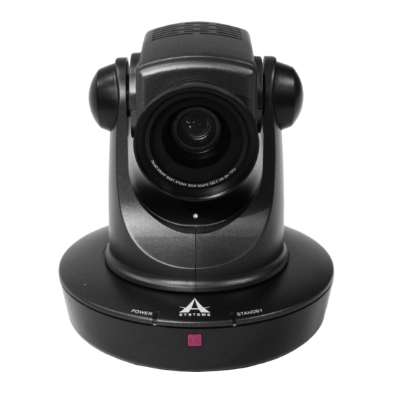
Page 7: Camera Anatomy
MK20HD PLUS / MK20W CAMERA ANATOMY Front View 144mm Tally Lights Power LED Standby LED Front IR Sensor Rear View DIP (30 to 60fps) Tally In RS422 IN POE, LAN and Rear IR Sensor Streaming SDI Out Kensington Lock Interface SD Card Slot... - Page 8 MK20HD PLUS / MK20W Top View swivel base Bottom View 75mm VESA Mount 90mm English...
-
Page 9: Check The Included Items
MK20HD PLUS / MK20W CHECK THE INCLUDED ITEMS Upon unboxing the product, please carefully inspect the included items, in the unlikely event of any missing or damaged items, please contact your authorized retailer/distributor for replacements. MK20HD Plus / MK20W POE Power Adapter User’s Manual Pan/Tilt/Zoom Camera MK20HD PLUS / MK20W IR Remote with 2 AAA Batteries Owner’s Manual Ceiling Mount Brackets (A & B) Tripod Mount Main Unit Mounting Screw (M4) x 4 Bracket Mounting Screws (M3) x 3 Drop Prevention Wire Screws (M3) x 2 Drop Prevention Wire English... -
Page 10: Precautions For Installation
MK20HD PLUS / MK20W PRECAUTIONS FOR INSTALLATION To Installation Personnel Read the “Installation Instructions” thoroughly and then perform the operation correctly and safely. Also, always read the “Read this first!” of this manual as they contain important information. After installation, give the “Owner’s Manual” to the customer for future use. Ensure that the installation work complies ● In locations such as kitchens where there are with the technical standards governing high concentrations of steam and grease. electrical equipment. ● In outdoor locations or hot places where the temperature will exceed 50 °C (122 °F). This unit is for indoor use only. - Page 11 Before proceeding is dissipated to the bottom panel which will warm with maintenance, be absolutely sure to up over time: This is normal and not indicative of disconnect the power plug from the power any trouble. outlet. Asystems does not assume any responsibility for accidents or damage resulting from installation procedures not being followed. English...
-
Page 12: Ceiling Mount Installation
MK20HD PLUS / MK20W CEILING MOUNT INSTALLATION The procedure given here is for the kind of installation where the unit is suspended from an overhead surface, but the same steps are followed for an upright stand-alone installation. If the ceiling panel is not strong enough to bear the unit’s weight, use the kind of mount bracket that is supported by anchor bolts between the concrete ceiling and ceiling panel. The unit supports the ceiling mount bracket which is used solely for combination cameras. Use this bracket to install the unit. For installing the ceiling mount bracket, the ceiling must be drilled. It is also recommended that you provide an inspection space or opening for access purposes in the area near where the equipment is installed in order to facilitate installation and the wiring connections work. - Page 13 MK20HD PLUS / MK20W 2. Mount the bracket (A) to the MK20HD Plus and MK20W camera. ● Use the bracket mounting M4 screws supplied with the unit to attach the bracket (A) to the VESA mount on the base of camera. Main unit mounting screws (M4) x 2 (supplied) (M4, bind-head) Screw diameter Clamping torque 1.47 N • m {15 kgf • cm} 3. Attach the drop prevention wire. ● Use the M3 drop prevention wire screws to attach the wire in the middle of the brackets. Drop prevention wire screws (M3) x 2 (supplied) English...
- Page 14 MK20HD PLUS / MK20W 4. Mount the unit. ● The hooks on bracket (B) can be inserted to the corresponding holes to bracket (A) to form a hinge, once inserted, turn the bracket (B) counterclockwise to lock it in place. 5. Secure the mounting brackets in place. ● Use the M3 screws on the exterior of the brackets to secure them in place. Bracket mounting screws (M3) x 3 (supplied) English...
-
Page 15: Tripod Mount Installation
MK20HD PLUS / MK20W TRIPOD MOUNT INSTALLATION For setups that require the camera to be mounted on a tripod, please use the following instructions to properly mount the camera. ● Before proceeding to install and connect the main unit, make sure the tripod legs are steadily and firmly set without wobbles. ● Make sure the tripod always maintains a 90 degree vertical center of gravity. A top-heavy object such as this is prone to tilt over and cause irreversible damage to the instrument, therefore, 90 degree vertical is the optimal angle for camera mounting. -
Page 16: Precaution For Use
MK20HD PLUS / MK20W PRECAUTION FOR USE ● Handle carefully Do not drop the product, or subject it to strong shock or vibration ● Use the product in an ambient temperature of 32 °F to 122 °F (0 °C to 50 °C). Avoid using the product at a cold place below 32 °F (0 °C) or at a hot place above 122 °F (50 °C). Extremely temperatures will adversely affect the delicate parts of the unit. Room temperature of 77°F ± 5° (25°C ± 5°) is recommended operation temperature. ● Power off before connecting or disconnecting cables. Be sure to switch the power off before plugging or unplugging the cables. ● Avoid humidity and dust. -
Page 17: How To Connect The Unit
MK20HD PLUS / MK20W HOW TO CONNECT THE UNIT 1. Connect the video output cable via Interface or SDI cable. 2. Connect the COM port to your controller if the camera is to be controlled by a PTZ remote control. 3. If LAN control mode is to be used, connect the POE connector to your hub/router. If connected via COM port, connect the POE port to the included POE power adapter. 4. Power on the camera by using the IR remote or a PTZ camera remote control to begin operation. Note: This unit does not have a power switch. The power turns on when its power plug is connected to a power outlet. When the power is turned on, the pan, tilt, zoom and focusing operations are performed. Before proceeding with maintenance, be absolutely sure to disconnect the power plug from the power outlet. -
Page 18: Ip Camera Matrix Setup Manager
MK20HD PLUS / MK20W IP CAMERA MATRIX SETUP SOFTWARE When using the MK20HD Plus and MK20W in LAN mode, it’s important to first set up your camera controller and cameras in the IP Camera Matrix Setup Manager. This can be downloaded from the Asystems website (www.asystems-sys.com) on the MK20RC Plus page. A download link can be found in the Resources tab. Installation First and foremost, the POE/LAN connector on your MK20HD Plus or MK20W needs to be connected to your LAN hub. After downloading the IP Camera Matrix Setup Manager Software archive from the Asystems website, simply extract the files to your desired folder. Installation is not required but the software should be copied into a dedicated directory. The software can be launched by double-clicking the IPCameraMatrix.exe application file. Operation When starting the software, users will be asked to enter an account name and password. The default values for these are “admin” and “admin.” Once logged in, go to the User submenu to change the account name and/or enter a new password. Controller Setup When setting up your system, your first step should be to scan for controllers. 1. Click the “1” in the Controllers column to open the “Scan” menu. 2. By default, the Scan function will search the IP Range from 192.168.1.1 to 254, but if your LAN uses a different a host bit (specifically the third number in the IP address), be sure to change accordingly. 3. Click “Scan” to begin scanning your local area network (LAN). Scanning the network may take a moment but will identify any MK20RC Plus controllers within your LAN. 4. Select your MK20RC Plus to assign it to Controller 1 in the software. Up to 3 controllers can be setup within the software at any time. 5. You can then move onto cameras or follow the steps above to assign up to 2 more controllers. English... - Page 19 MK20HD PLUS / MK20W Camera Setup By default, 5 camera fields will be displayed on screen within the software. This can be expanded by clicking the triangle to the left of the Camera column. 1. Like with the Controller, click a number field under “Cameras” to open the Scan menu. 2. Once your network is scanned, all currently connected and compatible cameras will be displayed. You can select a camera to be assigned to your selected Camera number. Once a camera is assigned it will turn red. Repeat with additional cameras. NOTE: Within the software, cameras are numbered 1 through 25. This is not the case for the MK20RC Plus as the cameras are separated into 5 banks of 5 cameras. That being the case, you can use the little table below to understand how cameras assigned in the software are assigned in the MK20RC Plus. IP Camera Matrix Setup Software MK20RC Plus Cameras 1 - 5 Bank 1 Cameras 6 - 10 Bank 2 Cameras 11 - 15 Bank 3 Cameras 16 - 20 Bank 4 Cameras 21 - 25 Bank 5 All cameras are then assigned as cameras 1 to 5 within their respective banks. Load and Send There’s one more step that needs to be done before your Asystems MK20HD Plus or MK20W are ready to operate with your cameras. After the Controllers and Cameras have been scanned and assigned accordingly, click the “Send” button to upload your settings to the camera and controllers themselves. After this is finished, the MK20RC Plus will be able to link to any of the connected MK20HD Plus and MK20W cameras. The IP Camera Matrix Setup Manager software is not necessary beyond this point,...
-
Page 20: Dip Switch Setting
MK20HD PLUS / MK20W DIP SWITCH SETTING The DIP Switch on the back of the MK20HD Plus and MK20W allow users to set a remote IR ID for the camera. DIP 4 and 5 are used setting the ID of the unit when setting the IR ID of the camera. Setting unit ID is particularly useful when multiple MK20HD Plus or MK20Ws are deployed in an area, and user can switch controls among multiple cameras with a single IR remote that comes included with the MK20HD Plus and MK20W. DIP 4 & 5: IR ID Interface IR Remote ID Setting DIP Switch Setting Remote ID # Pin 5 Pin 4 IR Remote ID: 2 As mentioned prior, only the first two levers are used for setting the IR remote ID 1 to 3. If the levers are down, they represent “off ”; if the levers are up, they represent “on”. The ID setting method follows a binary value system, please use the reference table below for correctly setting the IR remote ID. English... -
Page 21: Operating Precautions
MK20HD PLUS / MK20W OPERATING PRECAUTIONS Shoot under the proper lighting conditions When using the automatic functions To produce pictures with eye-pleasing colors, ● If “Full Auto” has been selected as the setting shoot under the proper lighting conditions. for Scene on the camera menu, for example, all the auto settings will be turned on, and The pictures may not appear with their proper manual operations will no longer be possible colors when shooting under fluorescent lights. for some of the items. - Page 22 MK20HD PLUS / MK20W Operating temperature range Personal computer used Avoid using the unit in cold locations where If the same image is displayed for a prolonged the temperature drops below 0°C (32°F) or period on a PC monitor, the monitor may hot locations where the temperature rises be damaged. Use of a screen saver is...
-
Page 23: Ir Remote
MK20HD PLUS / MK20W IR REMOTE The MK20HD Plus and MK20W come equipped with a remote control which can be used to remotely control the cameras. Check out the following points before using the wireless remote control. ● Point the wireless remote control at the unit’s wireless remote control IR sensor areas (shown in the figures), and operate it within a range of 10 meters (32.8 ft) from these areas. ● The signal sensing distance is reduced if the angle at which the wireless remote control signals are sensed is increased. The signal sensing sensitivity is approximately halved at an angle of 40 degrees from the front of the signal light sensing area. If the remote control is operated from the behind the unit, it may be either difficult or impossible to perform the desired operations. ● If the unit is installed near fluorescent lights, plasma monitors or other such products or if the unit is exposed to sunlight, the effects of the light may make it impossible for the unit to be operated using the wireless remote control. Be sure to follow the steps below for installation and use. ● Take steps to ensure that the light-sensing area will not be exposed to the light from fluorescent lights, plasma monitors or other such products or from the sun. ● Install the unit away from fluorescent lights, plasma monitors and other such products. English... -
Page 24: Camera Settings
MK20HD PLUS / MK20W CAMERA SETTINGS User can manually adjust the camera settings with the MENU button of the remote control. Whenever changes are made, user must save in order the register and apply the changes made by selecting item “20. SAVE & EXIT”. 1. VIDEO OUT: Set video output image resolution and frame rate. 2. ZOOM RATIO DISP: Turn the on screen display of zoom ratio on/off. 3. AWB: Set auto/manual white balance. 4. DAY & NIGHT: Switch among color, black & white and auto. 5. GAMMA (DAY): Set GAMMA (DAY) correction. 6. GAMMA (NGT): Set GAMMA (NGT) correction. 7. AUTO SENS UP: Turn AUTO SENS UP on/off, which allows the ability of seeing in near total darkness while retaining full color images. -
Page 25: Layout Of Wireless Remote Control Ir Sensor Areas
MK20HD PLUS / MK20W LAYOUT OF WIRELESS REMOTE CONTROL IR SENSOR AREAS Front View Rear View Interface Rear IR Sensor Front IR Sensor Top View English... -
Page 26: Ir Remote Parts And Functions
5. DISP Toggle on screen status display on and off. 6. PRESET MEMORY CALL BUTTONS 0 ‑ 9 MK20HD Plus and MK20W can store up to 10 preset memories, these are used to call the information on the unit’s directions and other settings that have been registered in the unit’s preset memories. Use the Preset Memory Call... - Page 27 ENTER button confirms the user selection. 13. PAN‑TILT BUTTONS AND MENU OPERATION BUTTONS ↑↓←→ ● These are used to change the MK20HD Plus or MK20W’s direction. The unit is tilted in the up/down direction using the ↑ and ↓ buttons and panned in the left/right direction using the ← and → buttons.
- Page 28 MK20HD PLUS / MK20W 19. ZOOM + & ‑ ZOOM + & - are used to adjust the lens zoom. The zoom is adjusted in the wide-angle using the - button and in the telephoto using the + button. 20. FOCUS + & ‑ FOCUS + & - are used to adjust the lens focus manually when the manual setting is established for the lens focus. The focus is adjusted in the far using the + button and in the near using the - button.
-
Page 29: Recording And Capture
MK20HD Plus Client Software 3. Add Camera(s) After logging into the software, you will see your In your browser, go to www.asystems-sys.com Live View page. When you first log in, there will and navigate to “Support” > “Downloads” section not be any currently active cameras. To add a to find the software download. Alternatively,... - Page 30 Select a date and search to find recordings for that day. 7. Configuration The configuration menu offers a number of options for operating the MK20HD Plus or MK20W. Starting with the local configuration that allows 2. Plug‑In Installation users to set recording/snapshot destinations, as Use of the MK20HD Plus or MK20W IE protocol well as recording file sizes.
- Page 31 MK20HD PLUS / MK20W Live Streaming Software 2. Open Broadcaster Software To add a new stream to OBS, click the + button This is an important feature of the MK20HD within the window at the bottom under Sources, Plus and MK20W. It’s one thing to bring up your then choose to add a “Media Source”. Name cameras on your local computer, but you can also and create a new Media Source and click OK to use the feed to live stream through the internet continue.
-
Page 32: Webcam Emulation Setup Guide
MK20HD PLUS / MK20W ASYSTEMS VIRTUAL WEBCAM EMULATION SETUP GUIDE Webcam Emulation In an age where everyday people are allowed to host their own channels talking about anything and everything of their interests by streaming videos live, a virtual webcam emulation has become an essential feature of compact video switchers. With Asystems’ diverse video switchers, we grant user the ability to stream and broadcast video live via the POE connector. When webcam emulation is established, user is able to use all streaming programs and services to stream and broadcast live recording through the internet with ease. Please refer to the following steps to begin webcam emulation setup procedures. Connect the computer to the RJ45 Video Download the NETCAM pack on Asystems’ Streaming connector in the back of the panel. website under the Download page (http:// Turn off private firewall & antivirus software www.asystems-sys.com/en/help/downloads/). ● Open the Control Panel on your computer ● First unzip the file and click “Yes” to install ● Then open the Windows Firewall the iNETCAM.exe executable file. ● Select Turn Windows Firewall on or off ● Turn off the firewall within the Private... - Page 33 ● Review your information and click the “Install” button to begin the installation. ● Enter the IP address into the box and you’re all set! ● A NETCAM desktop icon will be set after the installation, should you need to reset the IP address, just simply click on the ● Once the necessary files have all been desktop icon and repeat the last step successfully installed, click “Finish”. again. ● The first time you installed the CODECS, a window will automatically pop up asking whether you would like to the NETCAM IP address. Click “Yes”, and you will be prompted to enter the IP address that is assigned to your MK20HD Plus / MK20W in the System Status menu.
-
Page 34: Specifications
MK20HD PLUS / MK20W SPECIFICATIONS Features MK20HD Plus MK20W Type 1/2.8” Type Exmor™ CMOS 1/2.8” Type Exmor™ CMOS Pixels HD 2.4MPixels HD 2.4MPixels Illumination 0.4 Lux @ F1.6 0.4 Lux @ F1.6 White Balance Auto/Manual Auto/Manual Sensor Gain Control Auto/Manual Auto/Manual Back-light On/Off On/Off Compensation E-Shutter 1/1 to 1/10,000 sec 1/1 to 1/10,000 sec S/N Ratio >50 dB >50 dB Type Normal Wide Angle (0.39x magnifying) Viewing Angle 59° (W) to 3.3° (T) 82° (W) to 4.6° (T) -
Page 35: Troubleshooting
MK20HD PLUS / MK20W TROUBLESHOOTING 1. No Power. ● Ensure the POE power adapter is firmly plugged in and standby LED (Red) is lit. 2. No full tilt range. ● Level the mounting surface (Ensure the mounting surface has less than 30 degree of incline). ● Tilt axis is damaged. 3. PTZ camera won’t respond to IR remote control. ● Ensure camera’s placement is within controller’s operating range; ensure at least one of camera’s IR sensor has direct line of sight path to the controller. ● Avoid direct fluorescent light exposure to camera’s IR sensor. ● Incorrect camera IR ID and remote controller ID matching; ensure both camera and controller are set to the same IR ID number. 4. RS422 remote operation not functioning. ● Ensure camera ID is set to camera 1 and connected to RS422 port of controller (such as the MK20RC and MK20RC Plus). - Page 36 www.asystems-sys.com...
Need help?
Do you have a question about the MK20W and is the answer not in the manual?
Questions and answers