
Summary of Contents for Comelit LogiFire 41CPE112
- Page 1 TECHNICAL AND PROGRAMMING MANUAL LogiFire 41CPE112 Addressable fire panel art. 41CPE112 Passion.Technology. Design.
-
Page 2: Table Of Contents
41CPE112 Addressable Fire Alarm Panel – Installation and Programming Manual Table of Contents 1. INTRODUCTION ..............................4 1.1. General Description ..........................4 1.2. General Specifications ..........................4 1.2.1 General Technical Specifications ....................4 1.2.2 Possible Hardware Configurations ..................... 5 1.2.3 Environment ..........................5 1.2.4 Electrical Characteristics ...................... - Page 3 APPENDIX D ................................54 APPENDIX E ................................55 DoP No: 044 Comelit Group S.p.A. Via Don Arrigoni 5 - 24020 Rovetta S. Lorenzo BG Italy tel. +39 0346 750 011 - fax +39 0346 71436 email: info@comelit.it - export.department@comelit.it EN 54-2:1997/A1:2006/AC:1999; EN 54-4:1997/A2:2006/AC:1999 41CPE112 Intended for use in fire detection and fire alarm systems in and around buildings.
-
Page 4: Introduction
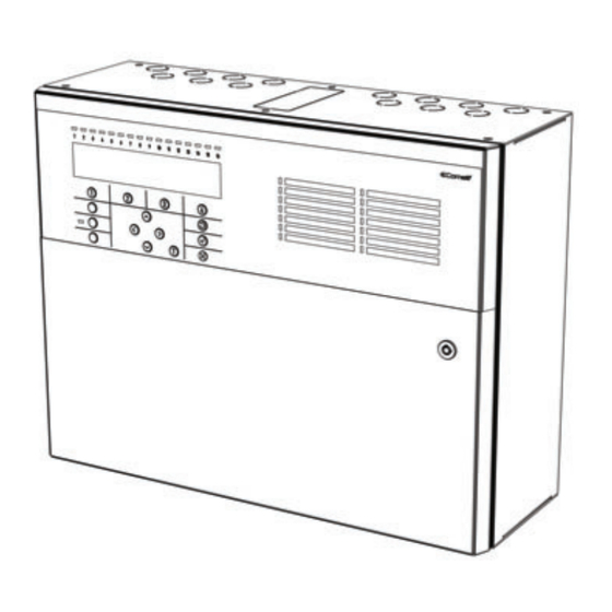
41CPE112 is an addressable fire panel with maximum coverage of 48 zones and up to 2 loops. The panel supports communication protocol Comelit and operation with Comelit addressable device series. Every Loop provides up to 250 devices (detectors and modules, regardless of the type). -
Page 5: Possible Hardware Configurations
41CPE112 Addressable Fire Alarm Panel – Installation and Programming Manual • 9 groups for zones’ organization • 5 monitored potential outputs: SND1 (Sounder 1) SND2 (Sounder 2) FIRE FAULT (The output is deactivated in case of fault event.) EXT (Extinguishing / Fire Protection – An output for sending an fire alarm signal to automatic fire extinguishing system) •... - Page 6 41CPE112 Addressable Fire Alarm Panel – Installation and Programming Manual Main power supply In normal operating conditions, the fire panel is powered from the mains voltage line. In case of mains voltage line loss the fire panel is equipped with one rechargeable battery. The characteristics of the main power supply are as follows: •...
-
Page 7: Installation
41CPE112 Addressable Fire Alarm Panel – Installation and Programming Manual 2. INSTALLATION 2.1. Wall Mounting • The panel must be installed in a clean dry place and must not be subjected to impact or vibrations (Figure 1). It must be situated far from heating appliances. The temperature must be within -5ºС and + 50ºC. The fire panel is not waterproof! •... -
Page 8: System Components
41CPE112 Addressable Fire Alarm Panel – Installation and Programming Manual • Use the template in the set to fix the mounting holes of the metal box on the wall. • Drill holes (suitable for anchors Ø6mm) on the wall and fix the metal box. •... - Page 9 41CPE112 Addressable Fire Alarm Panel – Installation and Programming Manual PROTECTION CONFIRMED EXTINGUISHING STARTED CONFIRMATION. Lights on permanently in (yellow) activation of the specialized “In PC” input – see the description on page 12. PROTECTION PANEL FAULT EXTINGUISHING SYSTEM FAULT. Lights on permanently in activation of the (yellow) specialized “In FP”...
-
Page 10: Configuration Of The Basic Modules
41CPE112 Addressable Fire Alarm Panel – Installation and Programming Manual 2.2.2 Configuration of the basic modules Figure 6 – Configuration of the modules in the box: 1 – Main PCB (control panel) 2 – Second loop controller (optional, it may not be present in your system configuration) 3 –... - Page 11 41CPE112 Addressable Fire Alarm Panel – Installation and Programming Manual • FAULT – Potential, monitored output for connection of auxiliary devices, 24 VDC/ 0.3А. This output is deactivated in case of system trouble or fault. • EXT - Potential, monitored output for fire extinguishing, 24 VDC/ 0.3А. This output is activated in case of a fire alarm condition.
-
Page 12: Connection Of Signaling Devices
41CPE112 Addressable Fire Alarm Panel – Installation and Programming Manual 2.3. Connection of Signaling Devices The monitored outputs SND, at activation, provide 24VDC@0,5A to the load connected between them and GND*. The monitored outputs FAULT, EXT and FIRE, provide 24VDC@0,3A to the load connected between them and GND*. -
Page 13: Loop Controller
Receives commands from the main microcontroller and transfers them to the devices connected in the communication line. Up to 250 Comelit devices can be connected to 41CPE112 loop controller. The general connection diagram of devices to the loop controller is shown on Figure 13. -
Page 14: Connecting To The Main Power Source
41CPE112 Addressable Fire Alarm Panel – Installation and Programming Manual 2.4. Connecting to the Main Power Source The mains power supply of 41CPE112 fire alarm panel is realized with connection of the main power cable to the 230V terminal, mounted in the metal box under the powers source. The connection between the 230V terminal and the main power source is done from the manufacturer. -
Page 15: Connecting A Network Module
3.1. Programming via LogiProg Software The specialized LogiProg software is designed for programming of intruder and fire alarm panels produced by Comelit. To program the fire alarm panel 41CPE112 you should first to install the LogiProg software on your computer – the... -
Page 16: Programming Via Panel's Keyboard
ATTENTION! The firmware update of the main microprocessor of fire alarm panel 41CPE112 should be performed by qualified personnel only and after held training program by the producer Comelit! 3.3.1 Firmware Update from Computer To start a firmware update from a computer you should first to have a copy of an image update file (with *.bin extension) saved on your computer. -
Page 17: Firmware Update From Usb Drive
41CPE112 Addressable Fire Alarm Panel – Installation and Programming Manual Ø The panel will reset itself automatically after a successful firmware update. 3.3.2 Firmware Update from USB Drive To start a firmware update from a USB drive you should first have to copy the new image update file (with *.bin extension) in the main directory of the USB removable disk. -
Page 18: Codes And Access Levels
41CPE112 Addressable Fire Alarm Panel – Installation and Programming Manual There is no access to the menus of the panel during that procedure. Upon the initial startup, the panel does not hold any configurations. Initialization may take several minutes. The initialization time needed depends on the number of periphery and loop devices –... - Page 19 41CPE112 Addressable Fire Alarm Panel – Installation and Programming Manual Access Level Mode/ Menu Description ü û û ALARMS Viewing the Alarms Messages in the system. Viewing the Faults Messages in the system. ü û û FAULTS ü û û DISABLED Viewing the active disablements in the system.
-
Page 20: Description Of The Operation Modes
41CPE112 Addressable Fire Alarm Panel – Installation and Programming Manual 6. DESCRIPTION OF THE OPERATION MODES In this section you can find detailed descriptions of all operation modes of 41CPE112 addressable fire alarm panel. The modes for reviewing of system events are accessible only from level 1 without entering access code. If no alarm, fault or warning messages, active tests and disablements are present, then the panel is in normal operation mode and only the current day and time is displayed. -
Page 21: Review Of Disablements
41CPE112 Addressable Fire Alarm Panel – Installation and Programming Manual 6.3. Review of Disablements The messages for disablements are displayed with normal priority. If no alarm or fault events are present, and there are active disablements in the system, the DISABLED mode is blinking together with the number of the first disablement. -
Page 22: Review Of Warning Messages
41CPE112 Addressable Fire Alarm Panel – Installation and Programming Manual After choosing the button (2) TESTS the screen displays: To exit the review of running tests mode, press CANCEL button. 6.5. Review of Warning Messages The messages for warnings are displayed with low priority. If no alarm or fault events or disablements and tests are present, and there are active warnings in the system, the WARNINGS mode is blinking together with the number of the first message. -
Page 23: Silencing The Internal Buzzer
41CPE112 Addressable Fire Alarm Panel – Installation and Programming Manual NOTE: If you are programming parameters at Access Level 2 (Maintenance) or Access Level 3 (Installer) and there is an alarm or fault event in the system, the panel will automatically display a list with messages. After reviewing the events, you can return to the programming mode with single pressing the CANCEL button. -
Page 24: Description Of The Programming Menus
41CPE112 Addressable Fire Alarm Panel – Installation and Programming Manual 7. DESCRIPTION OF THE PROGRAMMING MENUS The programming menus are accessible from level 2 (Maintenance) and level 3 (Installer) after entering a valid access code. In level 2 could be realized partial programming of parameters, and some values are accessible only for reviewing. In level 3 could be realized full programming and settings, and also to restore the factory default settings, including access codes. -
Page 25: Review Of List Of Events By Date
41CPE112 Addressable Fire Alarm Panel – Installation and Programming Manual 7.1.2 Review of List of Events by Date From the main screen of VIEW LOG menu press (2) FROM button. In “FROM” submenu the installer can extract a list of events by date. Set in sequence the day, the month and the last two digits of the year. The edited digit is flashing. Scroll between the fields using the left and the right arrows. -
Page 26: Zones Menu
41CPE112 Addressable Fire Alarm Panel – Installation and Programming Manual 7.2. Zones Menu This menu allows the installer to review and change the status of every zone. In the ‘ZONES’ menus the installer can test and enable/ disable the zones. Up to 48 zone numbers are available for settings. The currently edited zone number is blinking. -
Page 27: Disabling Zones
41CPE112 Addressable Fire Alarm Panel – Installation and Programming Manual 7.2.3 Disabling Zones From the main screen of ZONES menu, select a zone number using the up and down arrow buttons and press button (4) DISABLE. The zone status is changed to DISABLED – the panel stops following the status of the connected devices to the zone and will not alert for alarms and faults from them. -
Page 28: Programming Delays Т2
41CPE112 Addressable Fire Alarm Panel – Installation and Programming Manual • Examples for 2 DEVICES action mode operation: EXAMPLE 1 EXAMPLE 2 5 min 5 min Time Time 1 – An incoming alarm signal from Detector 1 and zone reset; 2 –... -
Page 29: Arranging Zones In Groups
41CPE112 Addressable Fire Alarm Panel – Installation and Programming Manual The set time delays T2 are confirmed with the ENTER button. 7.2.8 Arranging Zones in Groups The zones in 41CPE112 addressable fire alarm panel can be organized for operation in separate groups. The maximum number of the permissible groups is 9. -
Page 30: Saving The New Found Devices
41CPE112 Addressable Fire Alarm Panel – Installation and Programming Manual 7.3.2 Saving the New Found Devices The loop controller automatically recognizes the types of devices in the loop. In case of finding new devices in the system configuration (Loop 1 or Loop 2) the panel displays the message “ ”, followed by New Loop Devices Found information for the total number of the new devices and the loop number. -
Page 31: Fixing Of Wrong Type Devices
The 41CPE112 fire alarm addressable panel operates with full range of addressable detectors, call points, sounders and modules via Comelit communication protocol. According the type of the device, the setting parameters are different. Use the descriptions below to set the devices in your system configuration. - Page 32 41CPE112 Addressable Fire Alarm Panel – Installation and Programming Manual • Button ON/ OFF LED BLINK – Using this button the installer can enable or disable the LED indication showing the communication between the panel and the respective device. When setting ON state, the LED of the device starts blinking at every 10 seconds in normal operation mode.
- Page 33 41CPE112 Addressable Fire Alarm Panel – Installation and Programming Manual The exit to the main screen is with pressing the CANCEL button. 41RML100 / 41RML000 – Combined optical-smoke and heat detector with isolator Use the functional buttons to set the following specialized parameters: (1) SENSITIV.
- Page 34 41CPE112 Addressable Fire Alarm Panel – Installation and Programming Manual 41SAI000 – Wall mounted sounder with isolator Use the functional buttons to set the following specialized parameters: (1) SND LEVEL – Every pressing of the button alternatively changes the sound level between HIGH/ LOW – as this depends on the number of the connected sounders to the loop: - HIGH –...
- Page 35 41CPE112 Addressable Fire Alarm Panel – Installation and Programming Manual Attention: It is possible to connect different type of sounders to the loop at the same time, but the total consumption of the sounders in the loop must be up to 300mA! Note: The automatic detectors mounted to bases 41SCB100 are assigned at separate addresses in the control panel! 41SAB100 –...
- Page 36 41CPE112 Addressable Fire Alarm Panel – Installation and Programming Manual 41IOM010 – Mini input module The 41IOM010 is a compact module with one input. The module monitors and transfers to control panel the state of this input - state ON or state OFF. 41IOM010 is designed for built-in installation in the mounting box of a device. The activation of the 41IOM010 input can be programmed according the application.
- Page 37 41CPE112 Addressable Fire Alarm Panel – Installation and Programming Manual The installer has to choose an activation event using the up and down arrows. Use the left and right arrows to switch over the editable fields. • DEVICE - Activation from a device. Set the loop number and device address. The ‘INPUT’ field refers only to MIO modules.
- Page 38 41CPE112 Addressable Fire Alarm Panel – Installation and Programming Manual To associate IN 1/ 2 for operation in a group, press button (2) GROUP in the screen of the respective input number. In the editing field enter the group number using the up/ down arrow buttons. 41IOM040 –...
-
Page 39: Addressing Menus
(when operating with Comelit conventional detectors is a must to connect an EOL module at the end of the line). -
Page 40: Set Address
41CPE112 Addressable Fire Alarm Panel – Installation and Programming Manual - Auto Addressing by Isolators. This way requires all of the devices connected to the line to have a built-in or connected to the loop isolator module. The panel starts automatically setting address to the devices in increasing order from 1 to 250 by following the sequence of their position on the line. -
Page 41: Change Address
41CPE112 Addressable Fire Alarm Panel – Installation and Programming Manual 7.4.2 Change Address In this submenu the installer can change the address number of a device. To change address of a device, enter in the installer’s menu - 4. ADDRESSING - 4.2. CHANGE ADDRESS. The system automatically shows the first address in the system. -
Page 42: Panel Outputs Menus
41CPE112 Addressable Fire Alarm Panel – Installation and Programming Manual 7.5. Panel Outputs Menus This menu allows the installer to disable/ enable and to set time delay for some of the outputs of the control panel: - Sounder Outputs (SND 1, SND 2) - Extinguish Output (EXT) - Fire Output (FIRE) - Fault Output (FAULT) -
Page 43: Fire Output
41CPE112 Addressable Fire Alarm Panel – Installation and Programming Manual 7.5.3 Fire Output In this submenu the installer can disable/ enable the fire output activation and the time delay operation. To access the FIRE submenu, enter in the installer’s menu - 5. PANEL OUTPUTS - FIRE (3). Attention: In access level 2 you can only review the set delay status (ON/ OFF), with no rights to change it! The functional buttons have the following action: (2) - Press to change the status of the fire output. -
Page 44: General Settings Menu
41CPE112 Addressable Fire Alarm Panel – Installation and Programming Manual 7.6. General Settings Menu This menu allows the installer to make some common settings for the fire panel. The menu is accessible from access levels 2 and 3, as for the level to are introduced some restrictions. A list with submenus is displayed after entering the installer’s menu - 6. -
Page 45: Setting The Date And Time
41CPE112 Addressable Fire Alarm Panel – Installation and Programming Manual 7.6.2 Setting the Date and Time Attention: The setting of the date and time is available only from access level 3! In this submenu the installer can set the current time and date for the panel. To access the TIME/ DATE submenu, enter in the installer’s menu - 6. -
Page 46: Setting Day/ Night Alarm Modes
41CPE112 Addressable Fire Alarm Panel – Installation and Programming Manual 7.6.3 Setting Day/ Night Alarm Modes In this submenu the installer can set the operation alarm mode of the panel. To access the DAY/ NIGHT submenu, enter in the installer’s menu - 6. GENERAL SETTING - 6.3) DAY/ NIGHT. The screen displays: Press the functional button ‘2’... -
Page 47: Delay Т1
41CPE112 Addressable Fire Alarm Panel – Installation and Programming Manual 7.6.5 Delay Т1 In this submenu the installer sets the time to Delay T1. T1 is the time delay needed for reaction of the security personnel on the protected site. T1 provides a time delay for the personnel to go to the zone in fire alarm and to check the situation. -
Page 48: Company Logo
41CPE112 Addressable Fire Alarm Panel – Installation and Programming Manual - ON – Set this time interval from 1 to 600 seconds*. During evacuation mode the sounders will operate with the setting of (4) MORE button described above – for example when SND/FLASH option is set the sounders will sounding and flashing at the same time (for the models available). -
Page 49: Software Revision
41CPE112 Addressable Fire Alarm Panel – Installation and Programming Manual 7.9. Software Revision In this menu the installer can review the software versions of the main board and used loop modules and also has possibility for firmware update of the main processor unit. The screen displays: 7.10. -
Page 50: Active Isolators Menu
41CPE112 Addressable Fire Alarm Panel – Installation and Programming Manual Use the (3) CHANGE button to set the options: • NONE – The panel cannot send any commands to other panels in the redundant network. • COMMANDS – The panel can send commands to other panels in the redundant network. - Page 51 41CPE112 Addressable Fire Alarm Panel – Installation and Programming Manual Sounder1 Open Circuit broken at Sounder 1 output. Sounder2 Open Circuit broken at Sounder 2 output. Fire Output Short Short circuit detected at Fire output. Fire Output Fault Circuit broken at Fire output. EXT Output Short Short circuit detected at Extinguishing output.
- Page 52 41CPE112 Addressable Fire Alarm Panel – Installation and Programming Manual Network Fault Redundant network breakdown. Loop Device Disabled The loop device is disabled. Chamber Fault Fault in the detector. Clean Me Now Dirty detector chamber. Loop Device Input Fault Fault in loop device input. Loop Device Output Fault Fault in loop device output.
- Page 53 41CPE112 Addressable Fire Alarm Panel – Installation and Programming Manual APPENDIX C Initial power up of the system.
- Page 54 41CPE112 Addressable Fire Alarm Panel – Installation and Programming Manual APPENDIX D Two steps of alarming Algorithm.
- Page 55 41CPE112 Addressable Fire Alarm Panel – Installation and Programming Manual APPENDIX E Tree structure of the programming menus. The presented tree structure describes the full access to the programming menus from level 3 – Installer. From access level 2 – Maintenance, some of the programming menus are not displayed or the operation with them is partially limited –...
- Page 56 41CPE112 Addressable Fire Alarm Panel – Installation and Programming Manual Tree structure of the menus – continue.
- Page 57 Comelit Group S.p.A. Via Don Arrigoni 5 - 24020 Rovetta (BG) Italy www.comelitgroup.com...
Need help?
Do you have a question about the LogiFire 41CPE112 and is the answer not in the manual?
Questions and answers