Table of Contents
Advertisement
Quick Links
User Manual
19" 1440 x 900 Widescreen LCD
RMMWQ8190
8U Quad Display Panel
All rights reserved. Product description and product specifications are subject to change without notice.
For latest product information, please visit Acnodes' website at www.acnodes.com
14628 Central Ave. Chino, CA91710
Tel: 909.597.7588
Fax: 909.597.1939
© Copyright 2019 Acnodes Corp.
Advertisement
Table of Contents

Subscribe to Our Youtube Channel
Summary of Contents for Acnodes RMMWQ8190
- Page 1 19” 1440 x 900 Widescreen LCD RMMWQ8190 8U Quad Display Panel All rights reserved. Product description and product specifications are subject to change without notice. For latest product information, please visit Acnodes’ website at www.acnodes.com 14628 Central Ave. Chino, CA91710 Tel: 909.597.7588 Fax: 909.597.1939...
- Page 2 Legal Information First English printing, July 2019 Information in this document has been carefully checked for accuracy; however, no guarantee is given to the correctness of the contents. The information in this document is subject to change without notice. We are not liable for any injury or loss that results from the use of this equipment.
-
Page 3: Table Of Contents
Contents Contents < Part. 1 > RMWQ8190 Package Content Structure Diagram & Dimension P.1 - 2 Installation < Part. 2 > Specifi cations / OSD Product Specifi cations P.4 - 5 On-screen Display Operation ( OSD ) < Part. 3 > Options DC Power : 12V / 24V / 48V / 125V <... -
Page 4: Package Content
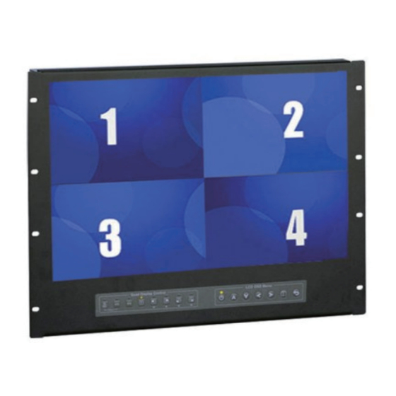
< Part 1 > < 1.1 > Package Content RMWQ8190 unit X 1 - 6ft VGA cable X 1 - Power adapter X 1 - Power cord X 1 < 1.2 > Structure Diagram Front view Power adapter Rear view LCD panel LCD OSD membrane Quad display control membrane... - Page 5 < 1.2 > Dimension Side View Front View UNIT : mm 1mm = 0.03937 inch Bottom View Product Dimension Packing Dimension Gross Model (W x D x H) (W x D x H) Weight Weight 480 x 72.5 x 354.8 mm 539 x 129 x 529 mm 9.5 kg 12.5 kg...
-
Page 6: Installation
< 1.3 > Installation Step ■ Mount the display panel with M6 screw set. ■ M6 screw x 8 pcs required ( Left & right side ). M6 screw sets are not provided. M en tr ol > C on <... -
Page 7: Product Specifi Cations
< Part 2 > < 2.1 > Product Specifi cations Manufacturer Panel Panel Size ( diagonal ) 19-inch Widescreen TFT color LCD Display pixel ( dots x lines ) 1440 x 900 Brightness ( typ. ) Contrast Ratio ( typ. ) 1000:1 Color 16.7 M... - Page 8 Product ( W x D x H ) 480 x 72.5 x 354.8 mm Physical Specifi cation 18.9 x 2.9 x 14 inch Packing ( W x D x H ) 539 x 129 x 529 mm 21.2 x 5.1 x 20.8 inch Net Weight 9.5 kg / 20.9 lb Gross Weight...
-
Page 9: On-Screen Display Operation ( Osd )
< 2.2 > On-screen Display Operation ( OSD ) LCD OSD Menu Power light Green = On Orange = Power saving Membrane Switch Function Power on / off LCD Display the OSD menu Scrolls through menu options and adjusts the displayed control (To auto adjustment by pressing the button for 5 seconds) Exit the OSD screen... -
Page 10: Part. 3 > Options
< Part 3 > < 3.1 > Options : DC Power Model 125V Input rating Input voltage: 12-Volt 24-Volt 48-Volt 110-Volt Input range: 9 ~ 18V 18 ~ 36V 36 ~ 75V 66 ~ 160V Input current - No load 50 mA 50 mA 50 mA... -
Page 11: Qd Connection
< Part 4 > < 4.1 > QD Connection 1. VCR in : This BNC connector is connected to video output from VCR/DVR. A pre-recorded quad screen signal from a tape can be played back through a VCR/DVR and displayed on the video output channels. Push the VCR button (#2) to switch the device to VCR Playback mode. -
Page 12: Qd Alarm Connection & Operation
< 4.2 > QD ALARM Connection & Operation 1. ALARM I/O : This female type 9 pin D-sub connector is used for alarm sensor input and alarm output control connections. It provides Normal Open and Normal Close contacts for alarm out control. Pin Assignment for Alarm Connector (female type) PIN# PIN#... - Page 13 < 4.2 > QD ALARM Connection & Operation 3 Sensor Activated Alarm The unit is equipped with 4 alarm sensor inputs. If any alarm is activated: ■ the built-in buzzer and the alarm output control relay contact will be activated. ■...
-
Page 14: Qd Remote Control Connection & Operation
< 4.3 > QD Remote Control Connection & Operation Rear Panel h i - z RS-232 1 2 3 4 ALARM monitor dc 12V, 1amp RS-232 Cable Wire Computer Remote Keypad P.11... - Page 15 < 4.3 > QD Remote Control Connection & Operation The device can be controlled via the male type 9 pin D-sub/RS-232 connector to a computer using ASCII code. 1. Pin assignment of the male type 9 pin D-sub connector: Pin Assignment for Remote Control Connector When a computer is used to control this device through a RS-232 port, pin 6, 7, 8, and 9 must be disconnected to prevent connecting the VCC and GND signals from the device to the computer.
- Page 16 < 4.3 > QD Remote Control Connection & Operation *1. In order to control the device to operate in Zoom mode, the computer has to fi rst send command code ” to switch the signal source from camera to VCR/DVR, at this time the device will automatically zoom channel 1 video from VCR/DVR to full screen.
- Page 17 < 4.3 > QD Remote Control Connection & Operation 2.3 The confi guration of the status code for both normal and alarm operations: There are total 2 bytes of the status codes. Byte one, the fi rst 8 bits, shows the current status of the operation modes that the unit is in.
- Page 18 < 4.3 > QD Remote Control Connection & Operation BYTE 2: Status code for alarm operations: The fi rst 4 bits show the sensor activated alarm status of each channel; next 4 bits show the video loss alarm status of each channel. The digit “1” means alarm event is detected, and “0”...
-
Page 19: Qd Osd Operation
< 4.4 > QD OSD Operation Quad Display Control Setup < > Lock: Security locks out button. Push this button for 2 seconds to enable control panel lock out function. Push this button again for 2 seconds to disable the function. VCR: Push this button to enter into VCR Playback/Zoom operation. -
Page 20: Qd On-Screen Menu
< 4.5 > QD On-screen Menu Right after the unit is turned on, The monitor will display the last setting on the Setup Menu. 1. Page 1 of the Setup Menu - Display Setting Push Setup buttons (#1, #2) simultaneously to display the Setup Menu on the screen. There are total two pages in the Setup Menu. - Page 21 < 4.5 > QD On-screen Menu 2 Page 2 of the setup menu- Alarm Setting Push Setup buttons (#1, #2) simultaneously and push (#1) button again to display page 2 of the setup menu on the screen. This Alarm Setting menu is used to set the desired alarm confi guration like sensor type, sensor sensitivity, alarm hold duration, and buzzer.
- Page 22 < 4.5 > QD On-screen Menu 4: The setup menu can be reset to factory setting by pushing the Setup buttons (#1, #2) and power on the quad simultaneously. The factory setting is as follows: TITLE DWELL TIME ALARM SETTING QUAD SENSOR TYPE...
-
Page 23: Qd Vcr Operation
< 4.6 > QD VCR Operation Zoom on VCR playback operation: Push VCR button (#2) to ON will switch the device to VCR playback mode. Under this mode, if the device is on quad display mode, a pr-recorded quad display video in the tape will be shown on the screen. If the device is in Full screen display mode, push any channel select buttons (#5) will select and expand the corresponding quadrants of the pre- recorded video to full screen display.
Need help?
Do you have a question about the RMMWQ8190 and is the answer not in the manual?
Questions and answers