Table of Contents
Advertisement
Quick Links
Advertisement
Table of Contents

Related Manuals for Picotest G5100AGC

Summary of Contents for Picotest G5100AGC
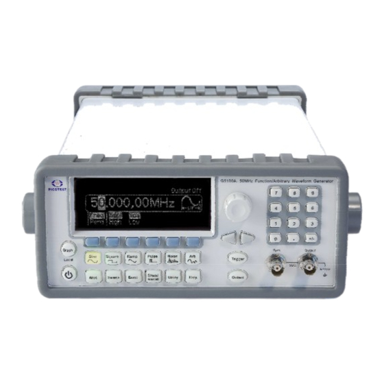
- Page 1 ® PICOTEST G5100A Arbitrary Waveform Generator Printed date: 05/2009...
-
Page 2: Table Of Contents
Table of Contents TABLE OF CONTENTS......................2 1 GENERAL INFORMATION....................6 1.1 F ....................... 6 EATURE VERVIEW 1.2 W ..................... 7 ARRANTY NFORMATION 1.3 P ..................8 RECAUTION OF PERATION 1.4 U G5100A...................... 9 PKEEP OF 1.5 S ....................9 AFETY NFORMATION 1.6 S... - Page 3 4.2 S ......................34 QUARE 4.3 R ........................35 4.4 N ....................... 36 OISE AVEFORM 4.5 P ......................37 ULSE AVEFORM 4.6 A ....................39 RBITRARY AVEFORM 4.7 A .................... 41 MPLITUDE ODULATION 4.8 F ................... 44 REQUENCY ODULATION 4.9 P ....................
- Page 4 7.8 A ................111 RBITRARY AVEFORM RRORS APPENDIX..........................113 ....................114 PECIFICATION ................. 120 EMOTE NTERFACE EFERENCE B.1.1 Command Format Used in This Manual..........120 B.1.2 Command Separators ................121 B.1.3 Using the MIN and MAX Parameters ............ 122 B.1.4 Querying Parameter Settings..............122 B.1.5 SCPI Command Terminators ..............
- Page 5 D. A ................... 173 PPLICATION ROGRAMS...
-
Page 6: General Information
Upkeep of G5100A Safety Information Symbols and Terms Inspection Options and Accessories You can contact Picotest Corp. via the following telephone number for warranty, service, or technical support information. Telephone: (886) 7-815-7183 Website http://www.picotest.com.tw Or contact Picotest for more help by email. -
Page 7: Warranty Information
4. Remarks: No other warranty is expressed or implied, except for the above mentioned. The remedies provided herein are the buyer’s sole and exclusive remedies. PICOTEST shall not be liable for any direct, indirect, special, incidental or consequential damages. -
Page 8: Precaution Of Operation
3. Our warranties do not apply on any direct, incidental, special, or consequential damages. 4. The above warranties are exclusive, and no other warranty is expressed or implied. Picotest disclaims any implied warranties of MERCHANTABILITY, SATISFACTORY QUALITY, and FITNESS for any particular reasons. -
Page 9: Upkeep Of G5100A
1.4 Upkeep of G5100A Although G5100A waveform generator is very durable and weather resistant, care should be taken not to expose it to severe impact or pressure. Keep G5100A far from water and damp environment. Calibration will be taken every year. Please contact your local service representative for more information. -
Page 10: Symbols And Terms
Do not try to operate the waveform generator if it is damaged. Disconnect the power from the equipment and consult the local service representative. Return the product to Picotest service department if necessary. 1.6 Symbols and Terms This symbol indicates hazards that may cause damages to the instrument or even result in personal injury. -
Page 11: Inspection
Optional accessories as you ordered. GPIB interface card. (Optional) 1.8 Options and Accessories The following options and accessories are available from Picotest for use with G5100A. Please refer to Table 1-1. Table 1-1 Accessory list. Part Name Part Number... -
Page 12: Overview
Overview This chapter prepares you for using the G5100A waveform generator. You may want to check if you have all the parts with your waveform generator first. All our products are handled and inspected professionally before shipping out to our customers. If you find any damaged/missing parts or have any doubts about the product, please contact your local service representative immediately and do not attempt to operate the damaged product. - Page 13 【Step 2】(Pull out the handle) When the handle is turned up to 90°, pull out the handle from the waveform generator as shown in Figure 2-2. Figure 1-2 Figure 2-2 Ⅱ. Adjusting the position for your convenience Here are some example positions for different needs. 【Position 1】...
- Page 14 【Position 2】 The adjusted position is for operation as shown in Figure 2-4. Figure 2-4 【Position 3】 The adjusted position is for carrying as shown in Figure 2-5. Figure 2-5...
-
Page 15: Factory Default Settings
2.2 Factory Default Settings Table 2-1 shows the factory default settings of G5100A when it is powered-on first time. Table 2-1 Factory default settings Parameters marked with a star ( * ) are stored in non-volatile memory. Output Configuration Default Setting Function Sine wave Frequency... - Page 16 Sweep 100 Hz/1 kHz Start/Stop Frequency 1 sec. Sweep Time Linear Sweep Mode Sweep State Burst Burst Count 1 Cycle Burst Period 10 ms Burst Start Phase 0 degree Burst State System-Related Operations Power-Down Recall Disabled Display Mode Error Queue 0 errors Stored States, Stored Arbs Output State...
-
Page 17: G5100A Operation Panels
2.3 G5100A Operation Panels Brief descriptions are provided in this chapter for all the connectors and buttons on both front and rear panels of G5100A waveform generator. 2.3.1 Front Panel Figure 2-6 Power Graph/Local Menu Operation Softkeys (in color grey) Waveform selection keys Modulation/Sweep/Burst keys Store/Recall Menu Key... -
Page 18: Rear Panel
2.3.2 Rear Panel Figure 2-7 1. 10MHz In (External 10 MHz Reference Input) Connector 2. 10MHz Out (Internal 10 MHz Reference Output) Connector 3. Modulation In (External Modulation Input) Connector 4. Trig In/Out, FSK/Burst Connector 5. LAN Port 6. GPIB Connector(Optional) 7. -
Page 19: Common Operations
Common Operations This chapter describes the basic operations and configurations that are commonly used to set up a waveform output. Operations for outputting specific waveforms are covered in chapter 4. 3.1 Graph Mode Pressing the Graph button enables the graph mode. You can view the waveform visually in the graph mode and change the waveform parameters by using the knob and the cursor keys. -
Page 20: T Oselect Output Function
a desired value directly on the numeric keypad or use the cursor keys to move the cursor on the display and increase or decrease the digit by turning the knob. When you use the numeric keypad, all the available units for the entry will be shown on the display. -
Page 21: To Set Output Frequency/Period
Remote Interface Operation FUNCtion {SINusoid|SQUare|RAMP|PULSe|NOISe|DC|USER|PATTern} You may also use the APPLy command to select the function, frequency, amplitude, and offset in one shot. Notes • Frequency limitation: When the newly-selected function has a smaller maximum frequency, the waveform generator will automatically adjust the frequency from the old value to the new, smaller maximum value. - Page 22 Front-panel Operation 1. Select your desired function by pressing one of the function keys. 2. Press the softkey under Freq/Perd and make sure Freq is highlighted (indicating the frequency mode is selected). 3. Use the numeric keypad or the knob with cursor keys to change the value.
-
Page 23: T Oset Output Amplitude
To Set Output Amplitude The default amplitude for all functions is 100 mVpp (into 50 ohms). The procedure to set a new amplitude value is described as follows. Figure 3-5 Front-panel Operation 1. Select your desired function by pressing one of the function keys. 2. - Page 24 • The default output unit is Vpp, but one may also choose from Vrms and dBm. But the output unit cannot be set to dBm if the output termination is set to “high impedance”. In such a case, the unit is automatically reset to Vpp.
-
Page 25: T Oset Dc Offset Voltage
switching of the output attenuators. The amplitude is controlled, however, so the output voltage will never exceed the current setting while switching ranges. You may disable the voltage autoranging to prevent this output disruption. To Set DC Offset Voltage The default DC offset voltage is 0 volt for all functions. To specify a non-zero DC offset value, follow the steps below. -
Page 26: To Set High-Level And Low-Level Bounds
Figure 3-8 • Limits with amplitude and output termination: DC offset value is constrained by the equation below: Voffset ≤ Vmax − where Vmax is the maximum peak voltage allowed for the selected output termination (5 volts for a 50 Ω load or 10 volts for a high-impedance load). -
Page 27: T Oset Waveform Polarity
5. Use the numeric keypad or the knob with cursor keys to change the value. 6. See Figure 3-6 and Figure 3-7 as sample displays. Remote Interface Operation VOLTage:HIGH {<voltage>|MINimum|MAXimum} VOLTage:LOW {<voltage>|MINimum|MAXimum} 3.8 To Set Waveform Polarity The default waveform polarity mode is Normal, in which the waveform goes positive during the first part of the wave cycle. -
Page 28: To Enable/Disable Voltage Autoranging
not match the value specified, the output amplitude and offset levels will be incorrect. To change this setting, follow the steps below. Front-panel Operation 1. Press the Utility button and then press the softkey under Output Setup. 2. Make sure the Load softkey is highlighted. If not, press the softkey to toggle. -
Page 29: T Ocontrol Output Connector
attenuator settings. To enable/disable voltage autoranging, follow the steps below. Front-panel Operation 1. Press the Utility button and then the softkey under Output Setup. 2. Press the softkey under Rang to toggle between Auto and Hold for auto-ranging setting. 3. Press the softkey under DONE to finish the selection. Figure 3-10 Figure 3-11 Remote Interface Operation... -
Page 30: To Enabled/Disable Sync Out Signal
Front-panel Operation • To enable/disable ouput, press the Output button to toggle. The Output button becomes lit when output is enabled. Remote Interface Operation OUTPut {OFF|ON} Notes • The Output is automatically disabled when an excessive external voltage is applied to the Output connector on the front panel and an error will be generated and the error message will be shown. - Page 31 Notes • If the Sync connector is disabled, the output signal is at a logic “low” level. • The Sync setting is stored in non-volatile memory, so it does not change after power-off or a remote reset command is issued. •...
-
Page 32: T Orestore The Factory Default Settings
burst count is infinite, the Sync signal works the same way described above for continuous waveforms. • If the burst generation is externally gated, the Sync signal starts at a TTL “high” with the external gate signal. However, the sync signal will not transition to a TTL “low”... -
Page 33: Waveform Output Operations
Waveform Output Operations This chapter describes each of the waveforms that G5100A provides and also the detailed front-panel, menu and remote interface operations for outputting the waveforms. 4.1 Sine Wave How to generate a sine wave 1. The default waveform output of G5100A is sine wave. To select sine wave while the current output function is not it, press the Sine button to make the selection. -
Page 34: Square Wave
4.2 Square Wave A square wave consists of instantaneous transitions between two voltage levels. The duty cycle of a square wave represents the amount of time in each cycle during which the wave is at the high level (assuming that the waveform is not inverted): DutyCycle = (Time Interval at High Level) / Period x 100% How to generate a square wave... -
Page 35: Ramp Wave
volatile memory. • When you change the output function from square wave to another, the previously-set duty cycle is remembered and will be resumed when square wave is re-selected. • For square waves with frequency higher than 10 MHz, the range of the duty cycle is from 40% to 60%, and for square waves with lower frequency, the range of the duty cycle is from 20% to 80%. -
Page 36: Noise Waveform
Remote interface operation APPLy:RAMP [<frequency>[,<amplitude>[,<offset>]]] (The command generates ramp wave with 100% symmetry) FUNCtion {RAMP} FREQuency {<frequency> ︱ MINimum ︱ MAXimum} VOLTage {<amplitude> ︱ MINimum ︱ MAXimum } VOLTage:OFFSet {<offset> ︱ MINimum ︱ MAXimum } FUNCtion:RAMP:SYMMetry {<percent>|MINimum|MAXimum} Notes • Symmetry value is stored in volatile memory so the default setting (100%) will be restored after power-off or a remote interface reset. -
Page 37: Pulse Waveform
VOLTage:OFFSet {<offset> ︱ MINimum ︱ MAXimum } Notes • In the APPL:NOIS command, the frequency parameter has no effect, but you still need to specify a value or “DEFault” for it. 4.5 Pulse Waveform A pulse waveform consists of a period, a pulse width, an ascending edge and a descending edge. - Page 38 PulsePerio ≤ ⎧ ⎪ < PulsePerio ≤ 100s ⎪ Wmin ⎨ μs, 100s < PulsePerio ≤ 1000s ⎪ ⎪ μs, 1000s < PulsePerio ⎩ If the specified value for PulseWidth is outside of the allowable range, the waveform generator will automatically adjust it to accommodate the given pulse period.
-
Page 39: Arbitrary Waveform
How to generate a pulse wave 1. Press the Pulse button to choose pulse wave output. 2. Refer to Chapter 3 for specifying the common parameters, including frequency/period, amplitude and dc offset voltage. 3. Press the softkey under Width/Duty to Toggle between setting pulse width or duty cycle. - Page 40 exponential-fall, negative-ramp, sinc, and cardiac. The default arbitrary waveform is an exponential-rise wave. For each user-defined waveform, one may create up to 262,144 (256k) points from the remote interface. If you choose an arbitrary waveform as the modulating waveform for AM, FM, PM, or PWM, the waveform is automatically limited to 4k points and the extra points will be removed by decimation.
-
Page 41: Amplitude Modulation
Figure 4-8 Remote interface operation FUNCtion USER {EXP_RISE | EXP_FALL | NEG_RAMP | SINC | CARDIAC} Remote interface operation DATA:DAC VOLATILE, {<binary block>|<value>, <value>, …} DATA VOLATILE, <value>, <value>, … FORMat:BORDer {NORMal ︱ SWAPped} DATA:COPY <destination arb name> [,VOLATILE] DATA:CATalog? DATA:NVOLatile:CATalog? DATA:NVOLatile:FREE? DATA:ATTRibute:AVERage? [<arb name>]... - Page 42 internal modulating waveform is sine wave. For internal source, one may also choose from square with 50% duty cycle, URamp (Up or Positive Ramp with 100% symmetry), DRamp (Down or Negative Ramp with 0% symmetry), triangle (ramp with 50% symmetry), noise and arbitrary waveforms.
- Page 43 (into a 50-ohm load) even if the modulation depth is greater than 100%. How to set up amplitude modulation 1. Press one of the following function buttons to choose your carrier waveform: Sine, Square, Ramp, Arb. Specify all the necessary waveform parameters for the carrier waveform as described in Section 4.1, 4.2, 4.3 and 4.6.
-
Page 44: Frequency Modulation
FUNCtion {SINusoid|SQUare|RAMP|USER} FREQuency {<frequency> ︱ MINimum|MAXimum} VOLTage {<amplitude> ︱ MINimum|MAXimum} VOLTage:OFFSet {<offset> ︱ MINimum|MAXimum} AM:INTernal:FUNCtion {SINusoid|SQUare|RAMP|NRAMp|TRIangle|NOISe|USER} AM:INTernal:FREQuency {<frequency> ︱ MINimum|MAXimum} AM:DEPTh {<depth in percent> ︱ MINimum ︱ MAXimum } AM:SOURce {INTernal|EXTernal} AM:STATe ON Notes • Only one type of modulation can be activated at one time. When amplitude modulation is enabled, the previously selected modulation is automatically disabled. - Page 45 ramp with 100% symmetry), DRamp (Down or Negative ramp with 0% symmetry), triangle (ramp with 50% symmetry), noise and arbitrary waveforms. If an arbitrary waveform is chosen, the number of points in the waveform is limited to 4k points with an automatic decimation process.
- Page 46 e.g., 100 kHz increase from carrier frequency if the specified frequency deviation is 100 kHz. When the external waveform is at -5v, the output will reach negative maximum frequency deviation; e.g., 100 kHz decrease from carrier frequency if the specified frequency deviation is 100 kHz.
-
Page 47: Phase Modulation
enter your value. 7. Press the Graph button to view all the waveform parameters. Remote interface operation Use these commands to output a frequency modulation waveform: FUNCtion {SINusoid|SQUare|RAMP|USER} FREQuency {<frequency> ︱ MINimum|MAXimum} VOLTage {<amplitude> ︱ MINimum|MAXimum} VOLTage:OFFSet {<offset> ︱ MINimum|MAXimum} FM:INTernal:FUNCtion {SINusoid|SQUare|RAMP|NRAMp|TRIangle|NOISe|USER} FM:INTernal:FREQuency {<frequency>MINimum|MAXimum}... - Page 48 Modulating Waveform G5100A accepts either internal or external modulating source but not both at the same time. The default source is internal, and the default internal modulating waveform is sine wave. For internal source, one may also choose from square with 50% duty cycle, URamp (Up or Positive ramp with 100% symmetry), DRamp (Down or Negative ramp with 0% symmetry), triangle (ramp with 50% symmetry), noise and arbitrary waveforms.
- Page 49 Figure 4-11 2. Press the Mod button to toggle on the modulation output. 3. Press the softkey under Type and press the softkey under PM to select phase modulation. A phase modulation output will be generated with the current parameters. 4.
-
Page 50: Fsk Modulation
PM:DEViation {<deviation in degrees> ︱ MINimum|MAXimum } PM:SOURce {INTernal|EXTernal} PM:STATe ON 4.10 FSK Modulation G5100A provides the capability to output FSK (Frequency-Shift Keying) modulation where the frequency of the waveform shifts between two frequencies (called “carrier frequency” and “hop frequency”). The shifting rate is determined by the internal or external modulating signal. - Page 51 the modulation is controlled by the signal level of the external waveform. When the external waveform is at the logic low level, the carrier frequency is outputted. When a logic high is present, the hop frequency is outputted. FSK Rate This is the rate at which the output frequency shifts between the carrier frequency and the hop frequency when internal source is selected.
-
Page 52: Pwm Waveform
Remote interface operation FUNCtion {SINusoid|SQUare|RAMP|USER} FREQuency {<frequency>|MINimum|MAXimum} VOLTage {<amplitude>|MINimum|MAXimum } VOLTage:OFFSet {<offset>|MINimum|MAXimum } FSKey: FREQuency {<frequency>|MINimum|MAXimum} FSKey:INTernal:RATE {<rate in Hz>|MINimum|MAXimum } FSKey:SOURce {INTernal|EXTernal} FSKey:STATe ON 4.11 PWM Waveform G5100A waveform generator provides the capability to output a pulse width modulation (PWM) for pulse carrier waveforms. In PWM, the pulse width of the pulse carrier waveform varies with the modulating waveform. - Page 53 with an external waveform coming from the Modulation In connector on the rear panel. Width Deviation The width deviation represents the peak variation in the pulse width of the modulation output based on that of the original pulse carrier waveform. The default deviation is 10μs, and the range is from 0s to 1000s.
-
Page 54: Frequency Sweep
source is depending on the previous waveform selection in arbitrary function. One may toggle the Mod key to see the arbitrary modulating waveform message that temporarily displayed on the screen. b. Press the softkey under PWM Freq and use numeric keypad or the knob with the cursor keys to set the desired modulating frequency. - Page 55 work with frequency sweep. Sweep Mode The default sweep mode is linear where the waveform generator sweeps the frequency with spacing calculated in a linear function. In logarithmic sweep mode, the waveform generator sweeps with spacing calculated in a logarithmic function. Start Frequency and Stop Frequency The waveform generator begins sweeping from the start frequency to the stop frequency.
- Page 56 Marker Frequency Marker frequency provides a way to control the Sync signal outputted on the front panel Sync connector. For sweeps with Marker On , the Sync signal is a TTL “high” at the beginning of the sweep and turns to “low” at the marker frequency.
- Page 57 cycle is outputted at the Trig Out connector with the sweep output. • With external trigger source, there is no signal outputted at the Ext Trig / FSK / Burst connector because it shares the same connector with Ext Trig for receiving the external trigger signal. •...
- Page 58 between Freq and OFF. If Freq is selected, Use the numeric keypad or the knob with cursor keys to set the marker frequency. 8. To configure the trigger setting, press the softkey under Trig Setup to enter the trigger setup menu: a.
-
Page 59: Burst Operation
or falling edge: TRIGger:SLOPe {POSitive|NEGative} Use the following commands to configure the Trig Out signal: OUTPut:TRIGger:SLOPe {POSitive|NEGative} OUTPut:TRIGger {OFF|ON} 4.13 Burst Operation G5100A offers the burst operation to generate the selected type of waveform with specified number of cycles, called a burst . Bursts may be triggered internally or manually. - Page 60 Table 4.13-1 The available parameters in each burst mode. Ext Trig Burst Burst Burst Signal Count Period Phase Polarity Internal √ √ √ Triggered mode External, √ √ Manual Gated mode √ √ Burst Count The Burst Count represents the number of cycles appeared in each burst. It is only used in the triggered burst mode.
- Page 61 mode, the waveform frequency is outputted when the external gate signal is true. The default waveform frequency is 1 kHz. The range is from 1 μHz to 200 kHz for ramps, 1 μHz to 25 MHz for square, 1 μHz to 10 MHz for pulse and arbitrary waveforms, 1 μHz to 50 MHz for Sine.
- Page 62 point, the output will remain at the same voltage level as the starting burst phase. Trigger Source The default trigger source is internal, and the available options are internal, external and manual. When the waveform generator is set to be in the triggered burst mode, it generates a burst with specific number of cycles each time a trigger is received.
- Page 63 2. Refer to Section 3.4 for specifying the waveform frequency for the selected function. 3. Press the Burst button to toggle the burst mode. 4. Press the N Cyc/Gated softkey to toggle between the triggered burst mode and the external gated mode. Make sure that your selection is highlighted.
-
Page 64: Pattern Output
4. If internal trigger source is selected, press the Burst Perd softkey and enter the desired burst period using the numeric keypad or the knob with the cursor keys. 5. Press the Graph button to view all the burst parameters. •... - Page 65 specified pattern of up to 256k points in 16-bit resolution. Similar to arbitrary waveforms, pattern output provides five built-in patterns and up to four user-defined patterns that are stored in non-volatile memory. built-in patterns exponential-rise, exponential-fall, negative-ramp, sinc, and cardiac. The default pattern output is an exponential-rise wave.
- Page 66 Setup to enter the trigger setup menu: a. To specify the trigger source, press the softkey under Src and then select among Ext (external) and Man (manual). b. If manual trigger is selected, you may configure the trigger out signal by pressing the softkey under Trig Out and then select among OFF, rising-edge trigger and falling-edge trigger.
- Page 67 Set the start address (min. 1) of the pattern. Set the end address of the pattern. Set the trigger source of the pattern, such as from EXT or BUS. (Please note that there is no IMM internal trigger. Set the Trigger slope of the pattern out to be a positive (rising) edge or a negative (falling) edge.
- Page 68 DIGital:PATTern:FREQuency {<frequency>, MINimum, MAXimum} Set the frequency of the pattern, 1uHz ~ 50MHz. DIGital:PATTern:FREQuency? {MINimum, MAXimum} Inquire and gain the minimum or maximum frequency of the pattern. DIGital:PATTern:STARt {<address>, MINimum, MAXimum} Set the start address (min. 1) of the pattern. DIGital:PATTern:STARt? {MINimum, MAXimum} Inquire and gain the start address of the pattern.
- Page 69 Inquire and gain the trigger source of the pattern. DIGital:PATTern:TRIGger:SLOPe {POS, NEG} Set the Trigger slope of the pattern to be a positive (rising) edge or a negative (falling) edge. DIGital:PATTern:TRIGger:SLOPe? Inquire and gain the trigger slope status of the pattern. DIGital:PATTern:OUTPut:TRIGger {OFF, ON} Set the trigger of the pattern out to be ON or OFF.
- Page 70 Pattern Generator Cable Pattern Generator Receiver Connector pin out structure of Pattern Generator Cable...
- Page 71 Schematic of Receiver...
-
Page 72: System Operations
System Operations 5.1 Triggering This feature is only available for bursts and sweeps. There are three options to choose from: internal triggering, external triggering and manual triggering. The default is the internal triggering in which the waveform generator continuously outputs the selected waveform. The Ext Trig connector on the rear panel is used to receive the external trigger signal. - Page 73 Slope to toggle between rising edge trigger and falling edge trigger. 2. Press DONE to finish the setting. Remote interface operation TRIGger:SLOPe {POSitive|NEGative} Software Triggering In software triggering, a bus command is sent through the remote interface to trigger the waveform generator. The waveform generator outputs a burst or a sweep when it receives one such command.
-
Page 74: Storing The Instrument State
current cycle and then stops at the same voltage level as the starting burst phase. For noise waveform, the output stops immediately when the external signal turns false. Trigger Out Signal G5100A may be configured to send out a TTL-compatible square wave at the Ext Trig connector on the rear panel with either a rising or a falling edge at the beginning of a sweep or burst. - Page 75 instrument state at power-down, but you can use any of these locations for storing a user-defined instrument state. The location “0” can only be accessed from the remote interface. Although you may store an instrument state in it, it is always preserved for power-down state. Anything previously stored in it will be overwritten with the power-down state when the waveform generator is turned off.
- Page 76 3. To recall a saved state, press the Recall State softkey to enter the recall-state submenu: a. Press the softkey under your desired location number to recall the state from that memory location. b. Press the Recall State softkey to restore from the selected state in the memory or the Cancel softkey to cancel.
-
Page 77: Display Control
6. To restore the instrument state to the factory default, press the softkey under Set to Def. A message will be displayed for you to confirm the action. Press the Yes softkey to confirm or the Cancel key to cancel the operation. See Figure 4-19. Remote interface operation *SAV {1|2|3|4} *RCL {1|2|3|4}... -
Page 78: Beeper
5.4 Beeper G5100A normally lets out a beeper when an error is detected. One may turn off the beep when needed. The beeper setting is stored in non-volatile memory, so the setting remains even after the waveform generator is turned off or the reset command is issued from the remote operation. -
Page 79: Error Display
5.6 Error Display The waveform generator can store up to 20 syntax or hardware errors in its error queue. Each error string may contain up to 255 characters. The waveform generator beeps every time it detects an error (unless the beeper is turned off). -
Page 80: Remote Interface Operations
Remote Interface Operations G5100A supports three remote interfaces: USB, LAN and GPIB (IEEE-488). For GPIB, you will need an additional GPIB interface card installed. This chapter describes the operations for setting up these remote interfaces and lists the SCPI (Standard Commands for Programmable Instrument) commands... -
Page 81: Lan Interface
not affected by power cycle or a remote interface reset command. Avoid using the same address for the GPIB interface card in your computer. How to set up GPIB interface 1. Press the Utility button and then the I/O softkey. 2. - Page 82 The smallest domain is a host itself. For example, domain “www.picotest.com.tw” consists of a host name “www” and three domains “picotest”, “com” and the country domain “tw”. The host name and names of its domains are concatenated with the period “.” in the full domain name of the host.
- Page 83 is not affected by power cycle or the remoter interface reset command. How to set up LAN interface 1. Press the Utility button and then the softkey under I/O. 2. Press the softkey under LAN to enter the LAN submenu. You have the options to set up IP address and related parameters (under the IP Setup softkey), DNS configuration (under the DNS Setup softkey) or to view the current LAN configuration (under the...
-
Page 84: Remote Interface Commands
DNS Setup Submenu 9. Press the softkey under DNS Setup to enter the submenu. 10. Host Name a. Press the softkey under Host Name to set the host name for your waveform generator. b. Use the numeric keys and the knob with the arrow keys to enter your desired letters or symbols. - Page 85 separates several choices for a parameter. The APPLy Commands APPLy:SINusoid [<frequency>[,<amplitude>[,<offset> ] ]] APPLy:SQUare [<frequency>[,<amplitude>[,<offset> ] ]] APPLy:RAMP [<frequency>[,<amplitude>[,<offset> ] ]] APPLy:PULSe [<frequency>[,<amplitude>[,<offset> ] ]] APPLy:NOISe [<frequency|DEF>[,<amplitude>[,<offset> ] ]] APPLy:DC [<frequency|DEF>[,<amplitude>[,<offset> ] ]] APPLy:USER [<frequency>[,<amplitude>[,<offset> ] ]] APPLy? Output Configuration Commands FUNCtion {SINusoid|SQUare|RAMP|PULSe|NOISe|DC|USER} FUNCtion? FREQuency {<frequency>|MINimum|MAXimum}...
- Page 86 OUTPut:POLarity {NORMal︱INVerted} OUTPut:POLarity? OUTPut:SYNC {OFF︱ON} OUTPut:SYNC? Pulse Configuration Commands PULSe:PERiod {<seconds>|MINimum|MAXimum} PULSe:PERiod? [MINimum|MAXimum] FUNCtion:PULSe:HOLD {WIDTh ︱ DCYCle} FUNCtion:PULSe:HOLD? [WIDTh ︱ DCYCle] FUNCtion:PULSe:WIDTh {<seconds>|MINimum|MAXimum } FUNCtion:PULSe:WIDTh? [ MINimum|MAXimum ] FUNCtion:PULSe:DCYCle {<percent>|MINimum|MAXimum } FUNCtion:PULSe:DCYCle ? [MINimum|MAXimum] FUNCtion:PULSe:TRANsition {<seconds>|MINimum|MAXimum } FUNCtion:PULSe:TRANsition? [MINimum|MAXimum ] Amplitude Modulation Commands AM:INTernal:FUNCtion{SINusoid ︱...
- Page 87 FM:DEViation {<peak deviation in Hz> ︱ MINimum ︱ MAXimum} FM:DEViation? [MINimum ︱ MAXimum] FM:SOURce {INTernal ︱ EXTernal} FM:SOURce? FM:STATe {OFF ︱ ON} FM:STATe? Phase Modulation Commands PM:INTernal:FUNCtion{SINusoid ︱ SQUare ︱ RAMP ︱ NRAMp ︱ TRIangle ︱ NOISe ︱ USER} PM:INTernal:FUNCtion? PM:INTernal:FREQuency {<frequency>...
- Page 88 PWM:DEViation? [MINimum ︱ MAXimum] PWM:DEViation:DCYCle {<deviation in percent>︱MINimum︱MAXimum} PWM:DEViation:DCYCle? [MINimum ︱ MAXimum] PWM:SOURce {INTernal ︱ EXTernal} PWM:SOURce? PWM:STATe {OFF ︱ ON} PWM:STATe? Sweeps Commands FREQuency:STARt {<frequency> ︱ MINimum ︱ MAXimum} FREQuency:STARt? [MINimum ︱ MAXimum] FREQuency:STOP{<frequency> ︱ MINimum ︱ MAXimum} FREQuency:STOP? [MINimum ︱ MAXimum] FREQuency:CENTer {<frequency>...
- Page 89 Burst Commands BURSt:MODE {TRIGgered ︱ GATED} BURSt:MODE? BURSt:NCYCles {<#cycles> ︱ INFinity ︱ MINimum ︱ MAXimum} BURSt:NCYCles? [MINimum ︱ MAXimum] BURSt:INTernal:PERiod {<seconds> ︱ MINimum ︱ MAXimum } BURSt:INTernal:PERiod? [MINimum ︱ MAXimum] BURSt:PHASe {<angle> ︱ MINimum ︱ MAXimum } BURSt:PHASe? [MINimum ︱ MAXimum] BURst:STATe {OFF ︱...
- Page 90 DATA:COPY <destination arb name> [, VOLATILE] FUNCtion:USER {<arb name> ︱ VOLATILE} FUNCtion:USER? FUNCtion USER FUNCtion? DATA:CATalog? DATA:NVOLatile:CATalog? DATA:NVOLatile:FREE? DATA:ATTRibute:AVERage? [<arb name>] DATA:ATTRibute:CFACtor? [<arb name>] DATA:ATTRibute:POINts? [<arb name>] DATA:ATTRibute:PTPeak? [<arb name>] Triggering Commands TRIGger:SOURce {IMMediate ︱ EXTernal ︱ BUS} TRIGger:SOURce? TRIGger *TRG For external source on “Ext Trig”...
- Page 91 MEMory:STATe:NAME? {1 ︱ 2 ︱ 3 ︱ 4} MEMory:STATe:DELete {1 ︱ 2 ︱ 3 ︱ 4} MEMory:STATe:RECall:AUTO {OFF ︱ ON} MEMory:STATe:RECall:AUTO? MEMory:STATe:RECall:SELect {0 ︱ 1 ︱ 2 ︱ 3 ︱ 4} MEMory:STATe:RECall: SELect? MEMory:STATe:VALid? {1 ︱ 2 ︱ 3 ︱ 4} MEMory:NSTates? Sysrem-related Commands SYSTem:ERRor?
- Page 92 PHASe? [MINimum ︱ MAXimum] PHASe:REFerence PHASe:UNLock:ERRor:STATe {OFF ︱ ON} PHASe:UNLock:ERRor:STATe? UNIT:ANGLe {DEGree ︱RADian } UNIT:ANGLe? Status Reporting Commands *STB? *SRE <enable value> *SRE? STATus:QUEStionable:CONDition? STATus:QUEStionable[:EVENt]? STATus:QUEStionable:ENABle <enable value> STATus:QUEStionable:ENABle? *ESR? *ESE <enable value> *ESE? *CLS STATus:PRESet *PSC {0 ︱ 1} *OPC Calibration Commands CALibration?
- Page 93 IEEE 488.2 Common Commands *CLS *CLS *CLS *ESE<enable value> *ESE? *ESR? *IDN? *LRN? *OPC *OPC? *PSC {0|1} *PSC? *RST *SAV{1 ︱ 2 ︱ 3 ︱ 4} *RCL{1 ︱ 2 ︱ 3 ︱ 4} *SRE <enable value> *SRE? *STB? *TRG *TST?
-
Page 94: Error Messages
Error Messages Error messages are issued when an incorrect remote command is sent to your G5100A waveform generator for execution. This may occur for reasons such as incorrect command syntax, giving the parameters of a command that violate some system constraints, hardware failures and so. -
Page 95: Command Errors
Remote interface operation Use this command to read one error from the error queue: SYSTem:ERRor? Use this command to clear all the errors in the error queue: *CLS 7.1 Command Errors -101 Invalid character An invalid character was detected in the command string. -102 Syntax error Invalid syntax was detected in the command string. - Page 96 -124 Too many digits A numeric parameter with too many digits (> 255) was detected. -128 Numeric data not allowed A numeric parameter was received when the waveform generator was expecting a string parameter. -131 Invalid suffix A suffix was incorrectly specified for a numeric parameter. -138 Suffix not allowed A suffix is not supported for this command.
-
Page 97: Execution Errors
7.2 Execution Errors -211 Trigger ignored AGET or *TRG was received but the trigger was ignored. -221 Settings conflict; turned off infinite burst to allow immediate trigger source An infinite burst count is only allowed when an external or bus (software) trigger source is used. - Page 98 automatically disabled. -221 Settings conflict; trigger output connector used by burst gate If you have enabled burst , and selected gated burst mode, the Trig Out signal is automatically disabled. -221 Settings conflict; trigger output connector used by FSK If you have enabled FSK and is using the external trigger source, the Trig Out signal is automatically disabled.
- Page 99 mode or modulation Only one modulation can be enabled at one time. -221 Settings conflict; FSK turned off by selection of other mode or modulation Only one modulation can be enabled at one time. -221 Settings conflict; FM turned off by selection of other mode or modulation Only one modulation can be enabled at one time.
- Page 100 -221 Settings conflict; not able to burst this function The waveform generator cannot generate a burst using the dc voltage function. -221 Settings conflict; not able to modulate noise, modulation turned off The waveform generator cannot generate a modulated waveform using the noise function.
- Page 101 pulse the duty cycle to accommodate the specified period. -221 Settings conflict; edge time decreased due to period The edge time has been decreased to accommodate the period. -221 Settings conflict; pulse width increased due to large period The waveform generator has adjusted the pulse width to a greater minimum determined by the current period.
- Page 102 -221 Settings conflict; FM deviation cannot exceed carrier The frequency deviation cannot exceed the carrier frequency, or the waveform generator will adjust the deviation to a maximum allowed value. -221 Settings conflict; FM deviation exceeds max frequency The sum of the carrier frequency and the deviation cannot exceed the maximum frequency for the chosen function plus 100 kHz (20.1 MHz for sine and square, 300 kHz for ramp, and 5.1 MHz for arbitrary waveforms).
- Page 103 limitation: |Voffset| + Vpp / 2 ≤ Vmax, it is adjusted automatically to the maximum dc voltage allowed with the specified amplitude. -221 Settings conflict; amplitude changed due to offset When the existing amplitude does not conform to the following limitation: |Voffset| + Vpp / 2 ≤...
- Page 104 -222 Data out of range; pulse duty cycle limited by period; value clipped to… The specified duty cycle does not conform to the following condition and is adjusted to accommodate the period: DutyCycle ≤ (1 – 1.6 x Edge time / Period) x 100% -222 Data out of range;...
- Page 105 The frequency is out of range and is adjusted to the maximum value allowed due to selection of ramp waveform. -222 Data out of range; pulse frequency; value clipped to upper limit The frequency is out of range and is adjusted to the maximum value allowed due to selection of pulse waveform.
- Page 106 lower boundary determined by the FM:DEV command. The carrier frequency must be greater than or equal to the frequency deviation. -222 Data out of range; marker confined to sweep span; value clipped to… The specified marker frequency is out of range and is adjusted to the start or stop frequency, whichever is closer.
-
Page 107: Device Dependent Errors
-222 Data out of range; PWM deviation limited by pulse parameters The PWM deviation (width or duty cycle) is adjusted to accommodate the current pulse parameters such as pulse width/duty cycle, period and edge time. -222 Data out of range; duty cycle; value clipped to… The square wave duty cycle is adjusted to within 20% to 80%. -
Page 108: Query Errors
-350 Queue overflow More than 20 errors were found and the error queue was full. 7.4 Query Errors -410 Query INTERRUPTED A command was received, but the output buffer contained data from a previous command (the previous data is lost). -420 Query UNTERMINATED A query command was sent to read the output buffer over the interface, but no such command that generates data to the output... -
Page 109: Self-Test Errors
7.6 Self-Test Errors 621 Self-test failed; square-wave threshold DAC A possible malfunctioning DAC, failed DAC multiplexer (U8_2) channels, or associated circuitry. 623 Self-test failed; dc offset DAC 624 Self-test failed; null DAC 625 Self-test failed; amplitude DAC A possible malfunctioning DAC, failed DAC multiplexer (U8_2) channels, or associated circuitry. -
Page 110: Calibration Errors
7.7 Calibration Errors 701 Calibration error; security defeated by hardware jumper The calibration security feature has been disabled by shorting the two “CAL ENABLE” pads on the internal circuit board. 702 Calibration error; calibration memory is secured The calibration memory is secured to disallow a calibration from performing. -
Page 111: Arbitrary Waveform Errors
7.8 Arbitrary Waveform Errors 770 Nonvolatile arb waveform memory corruption detected A checksum error was found in the non-volatile memory used to store arbitrary waveform. As a result, the arbitrary waveform cannot be retrieved. 781 Not enough memory to store new arb waveform; use DATA:DELETE All non-volatile memory locations are occupied. - Page 112 788 Cannot copy to VOLATILE arb waveform You can only use DATA:COPY command to copy from VOLATILE, not to VOLATILE. 800 Block length must be even The binary data are represented as 16-bit integers. They are sent in groups of two bytes (DATA:DAC VOLATILE command). 810 State has not been stored The storage location specified in the *RCL command was never used in previous *SAV commands.
-
Page 113: Appendix
Appendix This appendix contains the performance specifications of the G5100A. It covers the AC, DC, Resistance, Temperature, and Frequency/Period characteristics under a variety of conditions. It also contains the general characteristics and accuracy calculations for your convenience. A lot of efforts are made to make sure these specifications serve your needs for production, engineering and/or research purposes. -
Page 114: A Specification List
Specification List Display Graph mode for visual verification of signal settings Standard Sine, Square, Ramp, Triangle, Pulse, waveforms Noise, DC Capability Built-in arbitrary Exponential Rise and Fall, Negative waveforms ramp, Sin(x)/x, Cardiac WAVEFORM CHARACTERISTIC Sine Frequency 1 uHz to 50 MHz 0.1dB(<100KHz) Amplitude 0.15dB(<5MHz) - Page 115 distortion DC to 1 MHz 2, 4 Spurious -70 dBc (non-harmonic) 1 MHz to 50 MHz -70 dBc + 6 dB/octave Phase Noise -115/dBC/Hz, typical (10K Offset) when f ≥ 1MHz, V ≥ 0.1Vpp Frequency 1 uHz to 25 MHz Rise/Fall time <...
- Page 116 Sample Rate 125 MSa/s 30ns typical Rise/Fall Time Linearity < 0.1%of peak output Settling Time < 250ns to 0.5% of final value Jitter(RMS) 6ns + 30ppm Non-volatile 4 waveforms * 256K Points Memory COMMON CHARACTERISTIC Frequency Resolution 1uHz 10mVpp to 10Vpp in 50Ω Range 20mVpp to 20Vpp in Hi-Z Accuracy...
- Page 117 Frequency Level 100mVpp ~5Vpp Input Impedance 1KΩ typical, AC coupled Lock Time < 2 Sec External Lock Range 10 MHz Frequency Level 632mVpp (0dBm), typical Output Impedance 50Ω typical, AC coupled -360 º to +360 º Phase Offset Range 0.001 º Resolution Accuracy Modulation...
- Page 118 Carrier Pulse Source Internal / external Internal Sine, Square, Ramp, Triangle, Noise, Arb Modulation Frequency 2mHz to 20KHz (Internal) Deviation 0% ~ 100% of pulse width Carrier Sine, Square, Ramp, Arb Source Internal / external Internal 50% duty cycle Square Modulation Frequency 2mHz to 100KHz...
- Page 119 Pulse width > 400 ns Trigger Output 50 Ω typical Output Impedance Maximum rate 1MHz Fan-out ≤ 4 Picotest G5100As Pattern Mode CHARACTERISTIC Clock Maximum rate 50MHz Output Level TTL compatible into ≥ 2 KΩ Output 110 Ω typical Impedance...
-
Page 120: B Remote Interface Reference
Remote Interface Reference B.1 An Introduction to the SCPI Language SCPI (Standard Commands for Programmable Instruments) is an ASCII-based instrument command language designed for testing and measurement instruments. It is based on a hierarchical structure, also known as a tree system . In this system, associated commands are grouped together under a common node or root, thus forming subsystems . -
Page 121: Command Separators
Most commands (and some parameters) are expressed as a mixture of upper- and lower-case letters. The upper-case letters indicate the abbreviated part that must be specified for the command. For shorter program lines, send the abbreviated form. For better program readability, use the long form. -
Page 122: Using The Min And Max Parameters
A semicolon ( ; ) is used to separate commands within the same subsystem, and can reduce typing efforts. For example, sending the following command string: "BURSt:MODE TRIG ; NCYCles 10" is the same as sending the following two commands: "BURS:MODE TRIG"... -
Page 123: Scpi Command Terminators
You can also query the minimum or maximum start frequency allowed for the current waveform function as follows: "STAR? MIN" "STAR? MAX" Caution • If you send two query commands without reading the response from the first, then when you attempt to read the response, you may receive some data from the first response followed by the complete second response. - Page 124 Numeric Parameters Commands that require numeric parameters will accept all commonly used decimal representations of numbers including optional signs, decimal points, and scientific notation. Special values for numeric parameters like MINimum, MAXimum, and DEFault are also accepted. You can also send engineering unit suffixes with numeric parameters (e.g., Mhz or Khz).
-
Page 125: Output Data Formats
B.2 Output Data Formats Output data will be in one of formats shown in the table below. Type of Output Data Output Data Format Non-reading queries < 80 ASCII character string Single reading (IEEE-488) SD.DDDDDDDDESDD<nl> Multiple readings (IEEE-488) SD.DDDDDDDDESDD,...,...,<nl> Single reading (RS-232) SD.DDDDDDDDESDD<cr><nl>... - Page 126 --Triangle waveform has 50% symmetry. --Negative Ramp waveform has 0% symmetry. --If an Arbitrary(USER) waveform is chosen to be the modulating waveform, it is automatically limited to 4k points. Extra points are removed using decimation. AM:INTernal :FREQuency{<frequency>|MINimum|MAXimum} Specify the frequency of the modulating waveform. This applies only when the modulating source is internal.
- Page 127 the modulating signal is at +5v, and the output will be at the minimum amplitude when the modulating signal is at-5v. AM:SOURce? Query the modulating source in amplitude modulation. “INT” or “EXT” string indicating the modulating source will be returned. AM:STATe {OFF|ON} Disable or Enable the amplitude modulation.
- Page 128 setting, depending on which has been selected to “hold” (FUNC:PULS:HOLD command). However the waveform generator will adjust the pulse width or the edge time to comply with the frequency restrictions for pulse waveforms. APPLY: NOISe [<frequency︱DEF> [,<amplitude > [,<offset>] ]] Output Gaussian pulse wave with the specific frequency, amplitude and (dc) offset.
- Page 129 Specify the burst mode. The default is Triggered mode. In the triggered mode, the waveform generator outputs a waveform with specified number of cycles (burst count) each time a trigger is received from the specified trigger source. In the gated mode, the output waveform is either “on” or “off” based on the external signal level on the Ext Trig connector on the rear panel.
- Page 130 The burst count will be returned. The range is from 1 to 50,000, and 9.9E+37 is returned if Infinite is specified. BURSt:INTernal:PERiod {<seconds>|MINimum|MAXimum} Specify the burst period for bursts with internal (immediate) trigger source. The burst period is ignored when external or manual trigger source is enabled (or when the gated burst mode is chosen).
- Page 131 BURSt:STATe? “0” (OFF) or ”1” (ON) will be returned. BURSt:GATE:POLarity {NORMal|INVerted} Specify whether the waveform generator uses true-high or true-low logic levels on the rear-panel Ext Trig connector for an externally-gated burst. The default is NORM (true-high logic). BUTSt:GATE:POLarity? “NORM” or “INV” will be returned. -- C -- CALibration? Perform a calibration using the specified calibration value (CALibration:VALue...
- Page 132 (ON). CALibration:SETup <0︱1︱2︱3︱…︱94> Configure the waveform generator’s internal state for each of the calibration step to be performed. CALibration:SETup? Query the calibration setup number. Return a value from “0” to “94”. CALibration:STRing<quoted string> Record information about calibration. For instance, the name of the person who did the calibration, the date of the last calibration, or the date of next scheduled calibration.
- Page 133 The values -1 and +1 correspond to the peak values of the waveform • when the offset is zero volts. The maximum amplitude will be limited if the data points do not span • the full range of the output DAC (Digital-to-Analog Converter). The DATA command overwrites the previous waveforms in volatile •...
- Page 134 values between ±1 and therefore its maximum amplitude is 6.087 Vpp (into 50 ohms). The DATA:DAC command overwrites the previous waveform in volatile memory (and no error will be generated). Use the DATA:COPY command to copy the waveform to non-volatile memory. The on-volatile memory can store up to four user-defined waveforms.
- Page 135 the offset is 0 volts). The maximum amplitude will be limited if the data points do not span the full range of the output DAC (Digital-to-Analog converter). For example, the built-in sinc wave does not use the full range of binary values between ±8191 and thus its maximum amplitude is limited to 6.087 Vpp (into 50 Ω).
- Page 136 cannot delete an arbitrary waveform that is currently output, or an error will be generated. DATA:ATTRibute:AVERage? [<arb name>] Query the arithmetic average of all data points for the specified waveform (-1≤≤). The default waveform is the currently active one (FUNC:USER command).
- Page 137 the front-panel display overrides the display state. The display is automatically enabled when the waveform generator has been turned off or after *RST command, or when you return to local (front-panel) operation. The display state is saved when you store the instrument state using *SAV command.
- Page 138 FM:INTernal:FUNCtion? Query the modulating function used in frequency modulation. “SIN”, “SQU”, “RAMP”, “NRAM”, “TRI”, “NOIS” or ”USER” string indicating the modulating function will be returned. -- Square waveform has 50% duty cycle. --Ramp waveform has 100% symmetry --Triangle waveform has 50% symmetry. --Negative Ramp waveform has 0% symmetry.
- Page 139 automatically to the maximum value allowed. The sum of frequency deviation and the carrier frequency must not be greater than the maximum frequency of the function used plus 100 KHz (50.1 MHz for sine and 25.1 MHz for square, 300 kHz for ramp, and 10.1 MHz for arbitrary waveforms).
- Page 140 Disable or Enable the frequency modulation. To avoid multiple waveform changes, you can enable it after setting up the modulation parameters. The waveform generator allows only one of burst, sweep and modulations enabled at one time. As long as one is enabled, the other will be turned off. FM:STATe? “0”...
- Page 141 ramps, from 1µHz to 10 MHz for arbitrary waveforms, from 1µHz to 25 MHz for square, and from 1µHz to 50 MHz for sine. The default is 1 KHz. The minimum value is 1µHz and the maximum value is 50 MHz. FREQuency:STOP? [MINimum|MAXimum] The stop frequency in sweeps will be returned.
- Page 142 FSKey: FREQuency {<frequency>|MINimum|MAXimum} Specify the FSK alternate (or ”hop”) frequency. The range is from 1 μHz to 200 kHz for ramps, 1 μHz to 10 MHz for arbitrary waveforms, from 1µHz to 25 MHz for square, and from 1µHz to 50 MHz for sine, and the default is 100Hz. FSKey: FREQuency? [MINimum|MAXimum] Query the “hop”...
- Page 143 width and edge time restrictions apply.) If a command specifying the duty cycle is received, the duty cycle is converted into equivalent pulse width in seconds. If Pulse Width Modulation is turned on, the pulse width is held, and the width deviation is held too, as the period is varied. Duty cycle deviation commands are converted to width deviation values.
- Page 144 necessary to accommodate the period. From the remote interface, a “Setting conflict” error is generated and the pulse width is adjusted. The specified pulse width must be less than the difference between the period and the edge time. Pulse Width ≤Period – (1.6x Edge time) The waveform generator adjusts the edge time first, and then the width if necessary to accommodate the period.
- Page 145 where Wmin=20 ns when period is not greater than 10s. Wmin=200 ns when period is greater than 10 s, but not greater than 100s. Wmin=2μs when period is greater than 100d, not greater than 1000s. Wmin=20μs when period is greater than 1000s. The waveform generator adjusts the pulse duty cycle when needed to accommodate the specified pulse period.
- Page 146 Edge time ≤ 0.625 x Period x Duty cycle/100 FUNCtion:PULSe:TRANsition? [MINimum|MAXimum] Query the edge time. The edge time in seconds is returned. FUNCtion:RAMP:SYMMetry {<percent>︱ MINimum|MAXimum } Specify the symmetry percentage for ramp waves. Symmetry represents the amount of time per cycle that the ramp wave is rising (supposing the waveform polarity is not inverted).
- Page 147 FUNCtion:SQUare:DCYCle? [MINimum|MAXimum] Query the current duty cycle in percent. FUNCtion USER {<arb name>︱VOLATILE} Choose one of the five built-in arbitrary waveform functions, one of four user-defined waveforms, or the waveform currently downloaded to volatile memory. The names of the five built-in arbitrary waveforms are “EXP_RISE”, “EXP_FALL”, “NEG_RAMP”, “SINC”, and “CARDIAC”.
-
Page 148: I To O
FUNCtion? Query the selection made by FUNCtion USER command. One of the strings “SIN”, “SQU”, “RAMP”, “PULS”, “NOIS”, “DC”, and “USER” will be returned. -- I to O -- -- I -- *IDN? Query the waveform generator’s identification string which contains four fields separated by commas. - Page 149 so when the marker frequency is turned on ( and the sweep mode is also turned on), the OUTP:SYNC command is ignored. MARKer? “0” or “1” indicating the enable state of the frequency marker will be returned. MARKer:FREQuency {<frequency>︱MINimum︱MAXimum} Specify the marker frequency. The signal on the front-panel Sync connector goes to a logic low at the marker frequency during the sweep.
- Page 150 Erase the instrument state from the specified storage location, including the custom name specified to that location, if any, and restore the default name. You cannot recall the instrument state from a storage location that is empty or an error will be generated. MEMory:STATe:RECall:AUTO {OFF︱ON} This instrument doesn't support automatic recall of the power-down state.
- Page 151 triggered burst modes to provide a way to poll or interrupt the computer when the *TRG command is complete. *OPC? Returns “1” to the output buffer after the previous commands have been completed. Other commands can not be executed until this command completes.
- Page 152 to the front-panel Output connector. If the actual load impedance is different than the specified value, the displayed amplitude, offset and high/low levels will be incorrect. When the output termination is set to “high impedance”, you cannot • specify the output amplitude in dBm. The unit will be automatically converted to Vpp.
-
Page 153: P To Z
enabled by OUTP:TRIG command, a TTL-compatible square waveform with the specified edge is output from the Ext Trig connector on the rear panel at the beginning of the sweep or burst. For a pulse with a rising edge, use Positive and for a pulse with a falling edge, use Negative. - Page 154 waveform in order to change the phase relationship to the external signal to which it is currently locked. The phase adjustment for phase-lock applications is independent of the burst phase as set by the BURS:PHAS command. PHASe [MINimum MAXimum] ︱ Query the phase offset in degree or radians.
- Page 155 PM:INTernal:FUNCtion? Query the modulating function used in phase modulation. “SIN”, “SQU”, “RAMP”, “NRAM”, “TRI”, “NOIS” or ”USER” string indicating the modulating function will be returned. PM:INTernal:FREQuency {<frequency>|MINimum|MAXimum} Specify the modulating waveform frequency. This applies only the modulation source is internal (PM:SOUR INT). The range is from 2 mHz to 20 kHz and the default is 10 Hz.
- Page 156 PM:STATe {OFF|ON} Disable or enable Phase Modulation. The default is Off. To avoid multiple waveform changes, you can enable it after setting up the modulation parameters. Only one type of modulation can be activated at one time. Also when Phase modulation is activated, sweep or burst mode will be disabled.
- Page 157 another function, the period will be used on the new function. If you change to a function whose minimum period is greater than that for a pulse waveform, the period is adjusted to the minimum value allowed for the new function. For example, if you output a pulse waveform with a period of 200 ns and then change to the ramp function, the waveform generator will automatically adjust the period to 5 µs (the lower limit for ramps).
- Page 158 Width Deviation ≤ Period - Pulse Width – Wmin Where: Wmin = 20 ns for period ≤ 10 s. Wmin = 20 ns for period > 10 s, but ≤ 100 s. Wmin = 2 μs for period > 100 s, but ≤ 1000 s. Wmin = 20 μs for period >...
- Page 159 greater than the pulse duty cycle and is under the following constraints: Duty Cycle Deviation ≤ Duty Cycle – 100 Χ Minimum Width/Period Duty Cycle Deviation≤ 100 – Duty Cycle – 100 Χ Minimum Width/Period Where Wmin = 20 ns for period ≤ 10 s. Wmin = 20 ns for period >...
- Page 160 external source, the pulse waveform is modulated with an external waveform. The width/duty cycle deviation is controlled by the ±5V signal level shown on the Modulation In connector on the rear panel. It means that when the modulating signal is at +5V, the output will be at its maximum duty cycle, and when the modulating signal is at -5V, the output will be at its minimum duty cycle.
- Page 161 enables the front-panel display if it has been turned off. This command will abort a sweep or burst in progress. -- S -- *SAV {1︱2︱3︱4} Store the current instrument state to the specified non-volatile storage location. If there is any instrument state stored in the specified location, it will be •...
- Page 162 The number of discrete frequency points in the sweep will be calculated according to the specified sweep time. SWEepe:TIME? Query the sweep time. The sweep time in seconds will be returned. SWEep:STATe{OFF︱ON} Disable or enable the sweep mode. The default is Off. To avoid multiple waveform changes, you can enable it after setting up the modulation parameters.
- Page 163 SYSTem:COMMunicate:RLSTate {LOCal︱REMote︱RWLock} Set the remote/local state of the waveform generator over the LAN interface from a Telnet or socket session. Provides control analogous to the IEEE-488.2 commands such as GTL (Go To Local) over the GPIB and USB interfaces. The default is Local which sets the instrument state to local and removes any annunciator and locks the front-panel keyboard.
- Page 164 TRIGger Issue an immediate trigger from the remote interface. This command can trigger a sweep or burst with any available trigger source (TRIG:SOUR command). TRIGger:SOURce {IMMediate︱EXTernal︱BUS} Specify a trigger source for the triggered burst mode only. The waveform generator accepts a software (BUS) trigger, an immediate (internal) trigger, or a hardware trigger from the rear-panel EXT TRIG connector.
- Page 165 source will be returned. TRIGger:SLOPe {POSitive︱NEGative} Specify whether the rising (positive) or falling (negative) edge of the trigger signal is to be used for an externally-triggered sweep. The default is POS. TRIGger:SLOPe? Query the trigger slope. “POS” or “NEG” string indicating the trigger slope will be returned.
- Page 166 changed, the Output Amplitude is automatically adjusted. For instance, when you change the output termination from 50 ohms to “high impedance”, your offset voltage doubles, thus it affects your output amplitude, and when Output Termination has been changed from “high impedance”...
- Page 167 (5 volts for a 50Ω load or 10 volts for a high-impedance load). The function generator will take the new specified output amplitude, but the offset voltage may be reduced accordingly, and a “Settings conflict” error is generated. When the Output Termination Setting is changed, the offset limits are automatically adjusted.
- Page 168 will have an amplitude of 5 Vpp (with an associated offset voltage of -500 mV) when you set your high level to +2 Vpp and low level to -3 Vpp. When the Output Termination Setting is changed, the voltage levels are automatically adjusted.
- Page 169 VOLTage:LOW? [MINimum︱MAXimum] Query the low voltage level. VOLTage: RANGe:AUTO{OFF︱ON︱ONCE} Disable or enable the voltage auto-ranging. The default is “On” where the waveform generator selects an optimal setting for the output amplifier and attenuators. When the auto-ranging is “Off”, the current setting is used. The “ONCE”...
-
Page 170: Scpi Compliance Information
*WAI Wait for all pending operation to complete before executing any additional commands over the interface. B.4 SCPI Compliance Information This section encloses a list of commands that are device-specific to G5100A. Although not included in the 1999.0 version of the SCPI standard, these commands are designed with the SCPI format in mind and they follow all of the syntax rules of the standard. -
Page 171: Using Device Clear To Halt Measurements
*PSC {0|1} *PSC? *RCL<0 ︱ 1 ︱ 2 ︱ 3 ︱ 4> *RST *SAV<0 ︱ 1 ︱ 2 ︱ 3 ︱ 4> *SRE<NRf> *SRE? *STB? *TRG *TST? *WAI B.6 Using Device Clear to Halt Measurements Device Clear is a special IEEE-488 low-level bus message. It is designed to be used to return the waveform generator to a responsive state. -
Page 172: General Specifications
C. General Specifications item Limitation & description 100V/240V 50Hz~60Hz Power Supply Voltage 100V/120V 400Hz Power Requirements 50 VA Maximum 1) 0 ℃ /30%RH 2) 18 ℃ /40%RH 3) 23 ℃ /40%RH 4) 28 ℃ /40%RH Operating Humidity 5) 35 ℃ /80%RH 6) 50 ℃... - Page 173 Introduction Five example programs are included in this chapter to demonstrate controlling the PICOTEST G5100A using SCPI commands. All of these programs are written in Microsoft® Visual C++® 6.0 and use the NI-VISA. If you want to modify the example programs, or write your own programs and compile them, you will need to install the NI-VISA.
- Page 174 If the communication is via GPIB or LAN interface, you have to revise the following USB command 1). to be GPIB 2). or LAN 3). one. 1). char instrDesc[]="USB0::5710::5100::TW00009009::INSTR"; 2). char instrDesc[]="GPIB0::10:: INSTR"; //GPIB control,Address:10 3). char instrDesc[]="TCPIP0::192.168.0.123::inst0::INSTR";//IP address:192.168.0.123 Program Listings Example: A Simple Sine Waveform This program (found in the “Examples\Sine”...
- Page 175 viPrintf(vi,"*RST\n"); viPrintf(vi,"FUNCtion SINusoid\n"); //Select waveshape // Other options are SQUare, RAMP, PULSe, NOISe, DC, and USER viPrintf(vi,"OUTPut:LOAD 50\n"); //Set the load impedance in Ohms //(50 Ohms default) // May also be INFinity, as when using oscilloscope or DMM viPrintf(vi,"FREQuency 12500\n"); //Set the frequency.
- Page 176 if (status != VI_SUCCESS){ printf("Can not Open device:\"%s\"\n",instrDesc); return; // This program uses low-level SCPI commands to configure // the function gnerator to output an AM waveform. // This program also shows how to use "state storage" to // store the instrument configuration in memory. viPrintf(vi,"*RST\n");...
- Page 177 ViSession defaultRM,vi=0; ViStatus status; char instrDesc[]="USB0::5710::5100::TW00009009::0::INSTR"; viOpenDefaultRM (&defaultRM); status = viOpen(defaultRM,instrDesc, VI_NULL,VI_NULL, &vi); if (status != VI_SUCCESS){ printf("Can not Open device:\"%s\"\n",instrDesc); return; //This program sets up a linear sweep using a sinusoid //waveform. It sets the start and stop frequency and sweep //time.
- Page 178 time is then incremented. //A Pulse Waveform #include <visa.h> #include <stdio.h> #include <windows.h> void main (int argc,char *argv[]) ViSession defaultRM,vi=0; ViStatus status; char instrDesc[]="USB0::5710::5100::TW00009009::0::INSTR"; int i; viOpenDefaultRM (&defaultRM); status = viOpen(defaultRM,instrDesc, VI_NULL,VI_NULL, &vi); if (status != VI_SUCCESS){ printf("Can not Open device:\"%s\"\n",instrDesc); return;...
- Page 179 for(i=0;i<19;i++){ //Vary edge by 5 nsec steps viPrintf(vi,"PULSe:TRANsition %E\n",0.00000001 + i * 0.000000005); Sleep(300); //Wait 300 msec viClose (vi); viClose (defaultRM); Example: Pulse Width Modulation (PWM) This program (found in the “Examples\PWM” subdirectory on the CD-ROM) configures a pulse waveform with duty cycle, which is then slowly modulated by a triangle waveform.
- Page 180 //units (pulse width and deviation) rather than duty cycle //if preferred. viPrintf(vi,"*RST\n"); viPrintf(vi,"OUTPut:LOAD 50\n"); //Set the load impedance to // 50 Ohms (default) viPrintf(vi,"FUNCtion:SHAPe PULSe\n"); //Carrier waveshape is pulse viPrintf(vi,"FREQuency 5000\n"); //Carrier frequency is 5 kHz viPrintf(vi,"VOLTage:LOW 0\n"); //Set parameters to 5 V TTL viPrintf(vi,"VOLTage:HIGH 5\n");...
Need help?
Do you have a question about the G5100AGC and is the answer not in the manual?
Questions and answers