Table of Contents
Advertisement
Quick Links
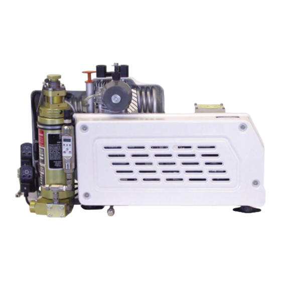
Yacht Pro Automatic Compressor
Operator's Manual
YP25DF & YP25SF
YP35DF & YP35SF
Brownie's Southport Divers
Brownie's Yacht Toys
Brownie's Palm Beach Divers
1530 Cordova Road
2301 South Federal Hwy
3619 Broadway
Fort Lauderdale, FL 33316
Fort Lauderdale, FL 33316
Riviera Beach, FL 33404
Ph 954.524.2112 Fx 954.524.7598
Ph 954.463.9446 Fx 954.524.6722
Ph 561.844.3483 Fx 561.845.1500
info@yachtdiver.com
Toll Free 800.949.0822
info@yachtdiver.com
Advertisement
Table of Contents

Related Manuals for Brownie’s YP25DF

Summary of Contents for Brownie’s YP25DF
- Page 1 Yacht Pro Automatic Compressor Operator’s Manual YP25DF & YP25SF YP35DF & YP35SF Brownie’s Southport Divers Brownie's Yacht Toys Brownie's Palm Beach Divers 1530 Cordova Road 2301 South Federal Hwy 3619 Broadway Fort Lauderdale, FL 33316 Fort Lauderdale, FL 33316 Riviera Beach, FL 33404 Ph 954.524.2112 Fx 954.524.7598...
-
Page 3: Preface
PREFACE Thank You for purchasing a Brownie’s Yacht Pro Series Compressor System. This manual explains the use and maintenance of your unit. All information here is based on the latest product data available at the time of publication. Brownie’s Third Lung reserves the right to make unannounced changes at any time without incurring any obligations whatsoever. -
Page 4: Table Of Contents
Table of Contents Preface Table of Contents Quality Analysis Product Data Description of Unit Standard Features Installation Pre Start-Up Checks Tankfill Procedures Purification System Lubrication Specifications Maintenance Schedule Torque Valves and Sequencing Valves Drive Belt V-belt Tension Adjustment Cooling System Oil Level Check Oil Types Intake Filter... -
Page 5: Quality Analysis
1 2 3 4 5 6 7 8 9 0 1 2 3 4 5 6 7 8 9 0 1 2 3 4 5 6 7 8 9 0 1 2 1 2 3 4 5 6 7 8 9 0 1 2 3 4 5 6 7 8 9 0 1 2 3 4 5 6 7 8 9 0 1 2 1 2 3 4 5 6 7 8 9 0 1 2 3 4 5 6 7 8 9 0 1 2 3 4 5 6 7 8 9 0 1 2 1 2 3 4 5 6 7 8 9 0 1 2 3 4 5 6 7 8 9 0 1 2 3 4 5 6 7 8 9 0 1 2 1 2 3 4 1 2 3 4 5 6 7 8 9 0 1 2 3 4 5 6 7 8 9 0 1 2 3 4 5 6 7 8 9 0 1 2 1 2 3 4 5 6 7 8 9 0 1 2 3 4 5 6 7 8 9 0 1 2 3 4 5 6 7 8 9 0 1 2 1 2 3 4 5 6 7 8 9 0 1 2 3 4 5 6 7 8 9 0 1 2 3 4 5 6 7 8 9 0 1 2 1 2 3 4 5 6 7 8 9 0 1 2 3 4 5 6 7 8 9 0 1 2 3 4 5 6 7 8 9 0 1 2 1 2 3 4 1 2 3 4 5 6 7 8 9 0 1 2 3 4 5 6 7 8 9 0 1 2 3 4 5 6 7 8 9 0 1 2 1 2 3 4 5 6 7 8 9 0 1 2 3 4 5 6 7 8 9 0 1 2 3 4 5 6 7 8 9 0 1 2 1 2 3 4 5 6 7 8 9 0 1 2 3 4 5 6 7 8 9 0 1 2 3 4 5 6 7 8 9 0 1 2 1 2 3 4 5 6 7 8 9 0 1 2 3 4 5 6 7 8 9 0 1 2 3 4 5 6 7 8 9 0 1 2 1 2 3 4 COMPRESSOR QUALITY ANALYSIS RECORD... -
Page 6: Product Data
1 2 3 4 5 6 7 8 9 0 1 2 3 4 5 6 7 8 9 0 1 2 3 4 5 6 7 8 9 0 1 2 1 2 3 4 5 6 7 8 9 0 1 2 3 4 5 6 7 8 9 0 1 2 3 4 5 6 7 8 9 0 1 2 1 2 3 4 5 6 7 8 9 0 1 2 3 4 5 6 7 8 9 0 1 2 3 4 5 6 7 8 9 0 1 2 1 2 3 4 5 6 7 8 9 0 1 2 3 4 5 6 7 8 9 0 1 2 3 4 5 6 7 8 9 0 1 2 1 2 3 4 Air Delivery Rate (a)(b): YP25DF 3.0 scfm, 2.5 FAD YP35DF 3.5 scfm, 3.0 FAD... -
Page 7: Description Of Unit
Dual Programmable Stainless Condensate Drain System Switch • Digital Frequency Drive Control System • One High Pressure Compressor with a 2HP (YP25DF) or 3HP (YP35DF) Motor • Stainless Programmable Digital Pressure Switch with LED Display • One Condensate Collection Jug •... -
Page 8: Installation
INSTALLATION WARNING: Improper installation may result in damage to the unit, personal injury or death. All persons operating the Yacht Pro Series system must read this manual completely and fully understand the procedures for system operation and the responsibilities of the operator to insure the safety of divers supplied with air from the system. -
Page 9: Pre Start-Up Checks
WARNING: Divers lives depend upon proper operation of the system. Brownie’s Third Lung highly recommends that all system operators take a System Training Course. PRE START-UP CHECKS Consult the system log to see if the following maintenance needs to be done: •... -
Page 10: Tankfill Procedures
Fill times are based on filling a single standard 80 cu ft aluminum cylinder from 500 psi to 3000 psi and are approximately as follows: YP25DF - 28 minutes per tank and YP35DF - 22 minutes per tank. Cylinder volume, starting tank pressure, and tank pressure ratings will vary the fill times. -
Page 11: Purification System
Explanation: The YP25DF and the YP35DF compress air in three stages. Air leaving the outlet (discharge) of each stage is at an elevated temperature. The air passes through cooling tubes and the temperature is reduced prior to entering the inlet of the next stage. -
Page 12: Maintenance Schedule
Recommended Maintenance WARNING: We recommend that any maintenance other than preventative be performed by an authorized service center or technician. Contact Brownie’s for service center information. MAINTENANCE TYPE OF MAINTENANCE DATE SERVICE INTERVAL CENTER After 25 hrs initially, and Oil Change (every 50 hours when using regular oil, every 50 - 100 hours and every 100 hours if using synthetics) or thereafter... -
Page 13: Torque Valves And Sequencing
TORQUE VALUES AND SEQUENCING Torque Values: Unless otherwise noted in text, the following torque values apply. All valve head screws require torque wrench tightening. The indicated values are for bolts in greased condition. Replace self-retaining nuts on reassembly. 1 2 3 4 5 6 7 8 9 0 1 2 3 4 5 6 7 8 9 0 1 2 3 4 5 6 7 8 9 0 1 2 1 2 3 4 5 6 7 8 9 0 1 2 3 4 5 6 7 8 9 0 1 2 3 4 5 6 7 8 9 0 1 2 1 2 3 4 5 6 7 8 9 0 1 2 3 4 5 6 7 8 9 0 1 2 3 4 5 6 7 8 9 0 1 2 1 2 3 4 5 6 7 8 9 0 1 2 3 4 5 6 7 8 9 0 1 2 3 4 5 6 7 8 9 0 1 2 1 2 3 4 1 2 3 4 5 6 7 8 9 0 1 2 3 4 5 6 7 8 9 0 1 2 3 4 5 6 7 8 9 0 1 2 1 2 3 4 5 6 7 8 9 0 1 2 3 4 5 6 7 8 9 0 1 2 3 4 5 6 7 8 9 0 1 2 1 2 3 4 5 6 7 8 9 0 1 2 3 4 5 6 7 8 9 0 1 2 3 4 5 6 7 8 9 0 1 2 1 2 3 4 5 6 7 8 9 0 1 2 3 4 5 6 7 8 9 0 1 2 3 4 5 6 7 8 9 0 1 2 1 2 3 4 1 2 3 4 5 6 7 8 9 0 1 2 3 4 5 6 7 8 9 0 1 2 3 4 5 6 7 8 9 0 1 2 1 2 3 4 5 6 7 8 9 0 1 2 3 4 5 6 7 8 9 0 1 2 3 4 5 6 7 8 9 0 1 2 1 2 3 4 5 6 7 8 9 0 1 2 3 4 5 6 7 8 9 0 1 2 3 4 5 6 7 8 9 0 1 2 1 2 3 4 5 6 7 8 9 0 1 2 3 4 5 6 7 8 9 0 1 2 3 4 5 6 7 8 9 0 1 2 1 2 3 4 1 2 3 4 5 6 7 8 9 0 1 2 3 4 5 6 7 8 9 0 1 2 3 4 5 6 7 8 9 0 1 2 1 2 3 4 5 6 7 8 9 0 1 2 3 4 5 6 7 8 9 0 1 2 3 4 5 6 7 8 9 0 1 2 1 2 3 4 5 6 7 8 9 0 1 2 3 4 5 6 7 8 9 0 1 2 3 4 5 6 7 8 9 0 1 2 1 2 3 4 5 6 7 8 9 0 1 2 3 4 5 6 7 8 9 0 1 2 3 4 5 6 7 8 9 0 1 2 1 2 3 4... -
Page 14: Valves
VALVES Valve Functioning The valve heads of the individual stages form the top part of the cylinders. The intake and pressure valves are fitted inside the valve heads. Note that the valves are operated by the flow of the gas. On the suction stroke, the intake valves open and the gas flows into the cylinders, and on the compression the intake valve closes, and gas flows out the pressure valve. - Page 15 CHANGING THE 2ND STAGE VALVES Both the pressure and intake valves can be serviced from the outside. • Remove two captive nuts (1) and springwashers (2). • Remove plate (3). • Remove valves (4) and (7) using two screwdrivers as shown in the diagram below.
-
Page 16: Drive Belt
CHECKING THE DRIVE BELT The best tension for belt drive is the lowest possible, while not slipping when under full load. This is best quantified by belt depression with thumb pressure between the two pulleys, with the belt deflecting ¼ “ (10mm) . •... -
Page 17: Oil Level Check
OIL LEVEL CHECK Check oil level daily prior to operating compressor. Use the dipstick and a lint free cloth to check the oil, by wiping off oil several times. Note that the oil level must be between the minimum and maximum dipstick notches. Add oil if necessary and recheck level. -
Page 18: Sightglass Element Change Demonstration
SIGHTGLASS CO MOISTURE ELEMENT CHANGE DEMONSTRATION Replacement Element Part # M7414 (Assy # VM211-EL) WARNING: Make sure all pressure is relieved prior to changing element. 1. Unscrew window cap in counter-clockwise 2. Here the cap is shown having been removed, direction. - Page 19 5. The CO monitoring disc is shown ready to 6. The spring is placed into the window, centered on the CO install into the window. It is placed in and then disc and the whole unit is then ready to be reassembled. centered in the moisture indicator ring.
-
Page 20: Black Filter Cartridge Replacement Demonstration
BLACK FILTER CARTRIDGE REPLACEMENT DEMONSTRATION REPLACEMENT CARTRIDGE PART #X53240 WARNING: Prior to changing the filter, purge all pressure using the bleeder valve. 1. Remove Cap Counter-clockwise rotation of the cap using a wrench 2. Remove Old Filter as shown will loosen the cap for removal. While removing the old filter, check the Lifeband ™... - Page 21 6. Replace Cap 5. Prepare to replace cap Clockwise rotation of the cap using a wrench as Inspect o-rings for damage and replace if necessary. shown will tighten the cap for replacement. Use a food grade silicone grease to lube threads and ring if needed.
-
Page 22: Gold Filter Cartridge Replacement Demonstration
GOLD FILTER TOWER CARTRIDGE REPLACEMENT DEMONSTRATION 2. Remove Cap 1. Vent Pressure Insert rod tool into holes in cap and Prior to changing the filter, purge all pressure using turn counter-clockwise. the bleeder valve. It may be necessary to vent excess pressure by turning the small cap on the gold tower clockwise. - Page 23 6. Lubricate O-ring Inspect o-rings for damage and replace if necessary. Use a food grade silicone grease to lube threads and ring if needed. 5. Install Cartridge Insert new cartridge making sure to push down as far as possible. Figure 2 Gold Filter Cartridge 7.
-
Page 24: Tankfill Demonstration
TANKFILL DEMONSTRATION Tank Fill Whip Assemblies: Shown are the tankfill whip ends for DIN and Yoke systems. A. Yoke connector B. DIN connector C. bleeder valve D. fill valve NOTE: Remember to check the system log before compressor use and to update the system log after you are done. 1. - Page 25 2. Close Bleeder Valves Clockwise rotation of the valve closes the bleeder valve. 3. Open Tank Valves Counter-clockwise rotation of this valve will open the tanks for filling. 4. Open Fill Valves Counter-clockwise rotation of this valve will open the line to the tanks.
- Page 26 NOTE: If you are filling more tanks, the compressor may be left “ON”. 6. Close Fill Lines Clockwise rotation of the knob closes off the fill lines. 7. Close Tanks Clockwise rotation of the knob closes the tank valves. 8. Open Bleeder Valves Counter-clockwise rotation of this valve will allow pressure to vent.
-
Page 27: Oil Change Demonstration
OIL CHANGE DEMONSTRATION 1. Remove the dipstick. 2. Removing the oil plug as demonstrated using one wrench to hold the tube and fitting and another to loosen the plug. 3. Remove the plug and allow the oil to drain. Care should be taken in draining the oil into a proper container for disposal per local guidelines and laws. - Page 28 Figure 3 Front and Back Compressor View...
- Page 29 Figure 4 Auto Drain System and Compressor Features Intermediate Separator Manual Drain Valve (normally closed) Gold Filter Tower Automatic Drain Solenoid Timer Gold Filter Tower Automatic Drain Solenoid Valve Intermediate Separator Automatic Drain Solenoid Timers Intermediate Separator Automatic Drain Solenoid Valve Inlet to Condensate Bottle Co/Moisture Indicator Sightglass Outlet to Fill Manifold...
-
Page 30: Parts Drawing 1
Parts Drawing 1... - Page 31 1 2 3 4 5 6 7 8 1 2 3 4 5 6 7 8 1 2 3 4 5 6 7 8 1 2 3 4 5 6 7 8 1 2 3 4 5 6 7 8 1 2 3 4 5 6 7 8 1 2 3 4 5 6 7 8 1 2 3 4 5 6 7 8...
-
Page 32: Parts Drawing 2
Parts Drawing 2... - Page 33 1 2 3 4 5 6 7 8 1 2 3 4 5 6 7 8 1 2 3 4 5 6 7 8 1 2 3 4 5 6 7 8 1 2 3 4 5 6 7 8 1 2 3 4 5 6 7 8 1 2 3 4 5 6 7 8 1 2 3 4 5 6 7 8...
-
Page 34: Parts Drawing 3
1 2 3 4 5 6 7 8 1 2 3 4 5 6 7 8 1 2 3 4 5 6 7 8 1 2 3 4 5 6 7 8 1 2 3 4 5 6 7 8 1 2 3 4 5 6 7 8 1 2 3 4 5 6 7 8 1 2 3 4 5 6 7 8... - Page 35 Figure 5 Black Filter Tower...
-
Page 36: Troubleshooting
TROUBLESHOOTING Warning: Compressor repairs are to be performed by an authorized dealer/service center only. Any repairs made by the user are to be made at the user’s own risk and will void Brownie’s Third Lung warranty unless the user has been authorized to make a repair and has been given appropriate repair instructions. Repairs must never be carried out without sufficient knowledge and understanding of compressor technology. - Page 37 PROBLEM CAUSE ACTION Intermediate pressure safety a) Intermediate pressure too a) Check / replace inlet or pressure valve valve blows high due to defective inlet or pressure valve of the next stage b) Safety valve leaking b) Replace safety valve Any taste in air a) Filter cartridge saturated a) Replace cartridge...
-
Page 38: Systems Operations Log
Yacht Pro Systems Operation Log NOTE: Check Maintenance Log for Service Intervals with each operation 1 2 3 4 5 6 7 8 9 0 1 2 3 4 5 6 7 8 9 0 1 2 3 4 5 6 7 8 9 0 1 2 1 2 3 4 5 6 7 8 9 0 1 2 3 4 5 6 7 8 9 0 1 2 3 4 5 6 7 8 9 0 1 2 1 2 3 4 5 6 7 8 9 0 1 2 3 4 5 6 7 8 9 0 1 2 3 4 5 6 7 8 9 0 1 2 1 2 3 4 5 6 7 8 9 0 1 2 3 4 5 6 7 8 9 0 1 2 3 4 5 6 7 8 9 0 1 2 1 2 3 4 1 2 3 4 5 6 7 8 9 0 1 2 3 4 5 6 7 8 9 0 1 2 3 4 5 6 7 8 9 0 1 2 1 2 3 4 5 6 7 8 9 0 1 2 3 4 5 6 7 8 9 0 1 2 3 4 5 6 7 8 9 0 1 2 1 2 3 4 5 6 7 8 9 0 1 2 3 4 5 6 7 8 9 0 1 2 3 4 5 6 7 8 9 0 1 2 1 2 3 4 5 6 7 8 9 0 1 2 3 4 5 6 7 8 9 0 1 2 3 4 5 6 7 8 9 0 1 2 1 2 3 4 1 2 3 4 5 6 7 8 9 0 1 2 3 4 5 6 7 8 9 0 1 2 3 4 5 6 7 8 9 0 1 2 1 2 3 4 5 6 7 8 9 0 1 2 3 4 5 6 7 8 9 0 1 2 3 4 5 6 7 8 9 0 1 2 1 2 3 4 5 6 7 8 9 0 1 2 3 4 5 6 7 8 9 0 1 2 3 4 5 6 7 8 9 0 1 2 1 2 3 4 5 6 7 8 9 0 1 2 3 4 5 6 7 8 9 0 1 2 3 4 5 6 7 8 9 0 1 2 1 2 3 4 1 2 3 4 5 6 7 8 9 0 1 2 3 4 5 6 7 8 9 0 1 2 3 4 5 6 7 8 9 0 1 2 1 2 3 4 5 6 7 8 9 0 1 2 3 4 5 6 7 8 9 0 1 2 3 4 5 6 7 8 9 0 1 2 1 2 3 4 5 6 7 8 9 0 1 2 3 4 5 6 7 8 9 0 1 2 3 4 5 6 7 8 9 0 1 2 1 2 3 4 5 6 7 8 9 0 1 2 3 4 5 6 7 8 9 0 1 2 3 4 5 6 7 8 9 0 1 2 1 2 3 4... - Page 39 Yacht Pro Systems Operation Log NOTE: Check Maintenance Log for Service Intervals with each operation 1 2 3 4 5 6 7 8 9 0 1 2 3 4 5 6 7 8 9 0 1 2 3 4 5 6 7 8 9 0 1 2 1 2 3 4 5 6 7 8 9 0 1 2 3 4 5 6 7 8 9 0 1 2 3 4 5 6 7 8 9 0 1 2 1 2 3 4 5 6 7 8 9 0 1 2 3 4 5 6 7 8 9 0 1 2 3 4 5 6 7 8 9 0 1 2 1 2 3 4 5 6 7 8 9 0 1 2 3 4 5 6 7 8 9 0 1 2 3 4 5 6 7 8 9 0 1 2 1 2 3 4 1 2 3 4 5 6 7 8 9 0 1 2 3 4 5 6 7 8 9 0 1 2 3 4 5 6 7 8 9 0 1 2 1 2 3 4 5 6 7 8 9 0 1 2 3 4 5 6 7 8 9 0 1 2 3 4 5 6 7 8 9 0 1 2 1 2 3 4 5 6 7 8 9 0 1 2 3 4 5 6 7 8 9 0 1 2 3 4 5 6 7 8 9 0 1 2 1 2 3 4 5 6 7 8 9 0 1 2 3 4 5 6 7 8 9 0 1 2 3 4 5 6 7 8 9 0 1 2 1 2 3 4 1 2 3 4 5 6 7 8 9 0 1 2 3 4 5 6 7 8 9 0 1 2 3 4 5 6 7 8 9 0 1 2 1 2 3 4 5 6 7 8 9 0 1 2 3 4 5 6 7 8 9 0 1 2 3 4 5 6 7 8 9 0 1 2 1 2 3 4 5 6 7 8 9 0 1 2 3 4 5 6 7 8 9 0 1 2 3 4 5 6 7 8 9 0 1 2 1 2 3 4 5 6 7 8 9 0 1 2 3 4 5 6 7 8 9 0 1 2 3 4 5 6 7 8 9 0 1 2 1 2 3 4 DATE...
- Page 40 Yacht Pro Systems Operation Log NOTE: Check Maintenance Log for Service Intervals with each operation 1 2 3 4 5 6 7 8 9 0 1 2 3 4 5 6 7 8 9 0 1 2 3 4 5 6 7 8 9 0 1 2 1 2 3 4 5 6 7 8 9 0 1 2 3 4 5 6 7 8 9 0 1 2 3 4 5 6 7 8 9 0 1 2 1 2 3 4 5 6 7 8 9 0 1 2 3 4 5 6 7 8 9 0 1 2 3 4 5 6 7 8 9 0 1 2 1 2 3 4 5 6 7 8 9 0 1 2 3 4 5 6 7 8 9 0 1 2 3 4 5 6 7 8 9 0 1 2 1 2 3 4 1 2 3 4 5 6 7 8 9 0 1 2 3 4 5 6 7 8 9 0 1 2 3 4 5 6 7 8 9 0 1 2 1 2 3 4 5 6 7 8 9 0 1 2 3 4 5 6 7 8 9 0 1 2 3 4 5 6 7 8 9 0 1 2 1 2 3 4 5 6 7 8 9 0 1 2 3 4 5 6 7 8 9 0 1 2 3 4 5 6 7 8 9 0 1 2 1 2 3 4 5 6 7 8 9 0 1 2 3 4 5 6 7 8 9 0 1 2 3 4 5 6 7 8 9 0 1 2 1 2 3 4 1 2 3 4 5 6 7 8 9 0 1 2 3 4 5 6 7 8 9 0 1 2 3 4 5 6 7 8 9 0 1 2 1 2 3 4 5 6 7 8 9 0 1 2 3 4 5 6 7 8 9 0 1 2 3 4 5 6 7 8 9 0 1 2 1 2 3 4 5 6 7 8 9 0 1 2 3 4 5 6 7 8 9 0 1 2 3 4 5 6 7 8 9 0 1 2 1 2 3 4 5 6 7 8 9 0 1 2 3 4 5 6 7 8 9 0 1 2 3 4 5 6 7 8 9 0 1 2 1 2 3 4 1 2 3 4 5 6 7 8 9 0 1 2 3 4 5 6 7 8 9 0 1 2 3 4 5 6 7 8 9 0 1 2 1 2 3 4 5 6 7 8 9 0 1 2 3 4 5 6 7 8 9 0 1 2 3 4 5 6 7 8 9 0 1 2 1 2 3 4 5 6 7 8 9 0 1 2 3 4 5 6 7 8 9 0 1 2 3 4 5 6 7 8 9 0 1 2 1 2 3 4 5 6 7 8 9 0 1 2 3 4 5 6 7 8 9 0 1 2 3 4 5 6 7 8 9 0 1 2 1 2 3 4...
- Page 41 Yacht Pro Systems Operation Log NOTE: Check Maintenance Log for Service Intervals with each operation 1 2 3 4 5 6 7 8 9 0 1 2 3 4 5 6 7 8 9 0 1 2 3 4 5 6 7 8 9 0 1 2 1 2 3 4 5 6 7 8 9 0 1 2 3 4 5 6 7 8 9 0 1 2 3 4 5 6 7 8 9 0 1 2 1 2 3 4 5 6 7 8 9 0 1 2 3 4 5 6 7 8 9 0 1 2 3 4 5 6 7 8 9 0 1 2 1 2 3 4 5 6 7 8 9 0 1 2 3 4 5 6 7 8 9 0 1 2 3 4 5 6 7 8 9 0 1 2 1 2 3 4 1 2 3 4 5 6 7 8 9 0 1 2 3 4 5 6 7 8 9 0 1 2 3 4 5 6 7 8 9 0 1 2 1 2 3 4 5 6 7 8 9 0 1 2 3 4 5 6 7 8 9 0 1 2 3 4 5 6 7 8 9 0 1 2 1 2 3 4 5 6 7 8 9 0 1 2 3 4 5 6 7 8 9 0 1 2 3 4 5 6 7 8 9 0 1 2 1 2 3 4 5 6 7 8 9 0 1 2 3 4 5 6 7 8 9 0 1 2 3 4 5 6 7 8 9 0 1 2 1 2 3 4 1 2 3 4 5 6 7 8 9 0 1 2 3 4 5 6 7 8 9 0 1 2 3 4 5 6 7 8 9 0 1 2 1 2 3 4 5 6 7 8 9 0 1 2 3 4 5 6 7 8 9 0 1 2 3 4 5 6 7 8 9 0 1 2 1 2 3 4 5 6 7 8 9 0 1 2 3 4 5 6 7 8 9 0 1 2 3 4 5 6 7 8 9 0 1 2 1 2 3 4 5 6 7 8 9 0 1 2 3 4 5 6 7 8 9 0 1 2 3 4 5 6 7 8 9 0 1 2 1 2 3 4 DATE...
- Page 42 Yacht Pro Systems Operation Log NOTE: Check Maintenance Log for Service Intervals with each operation 1 2 3 4 5 6 7 8 9 0 1 2 3 4 5 6 7 8 9 0 1 2 3 4 5 6 7 8 9 0 1 2 1 2 3 4 5 6 7 8 9 0 1 2 3 4 5 6 7 8 9 0 1 2 3 4 5 6 7 8 9 0 1 2 1 2 3 4 5 6 7 8 9 0 1 2 3 4 5 6 7 8 9 0 1 2 3 4 5 6 7 8 9 0 1 2 1 2 3 4 5 6 7 8 9 0 1 2 3 4 5 6 7 8 9 0 1 2 3 4 5 6 7 8 9 0 1 2 1 2 3 4 1 2 3 4 5 6 7 8 9 0 1 2 3 4 5 6 7 8 9 0 1 2 3 4 5 6 7 8 9 0 1 2 1 2 3 4 5 6 7 8 9 0 1 2 3 4 5 6 7 8 9 0 1 2 3 4 5 6 7 8 9 0 1 2 1 2 3 4 5 6 7 8 9 0 1 2 3 4 5 6 7 8 9 0 1 2 3 4 5 6 7 8 9 0 1 2 1 2 3 4 5 6 7 8 9 0 1 2 3 4 5 6 7 8 9 0 1 2 3 4 5 6 7 8 9 0 1 2 1 2 3 4 1 2 3 4 5 6 7 8 9 0 1 2 3 4 5 6 7 8 9 0 1 2 3 4 5 6 7 8 9 0 1 2 1 2 3 4 5 6 7 8 9 0 1 2 3 4 5 6 7 8 9 0 1 2 3 4 5 6 7 8 9 0 1 2 1 2 3 4 5 6 7 8 9 0 1 2 3 4 5 6 7 8 9 0 1 2 3 4 5 6 7 8 9 0 1 2 1 2 3 4 5 6 7 8 9 0 1 2 3 4 5 6 7 8 9 0 1 2 3 4 5 6 7 8 9 0 1 2 1 2 3 4 1 2 3 4 5 6 7 8 9 0 1 2 3 4 5 6 7 8 9 0 1 2 3 4 5 6 7 8 9 0 1 2 1 2 3 4 5 6 7 8 9 0 1 2 3 4 5 6 7 8 9 0 1 2 3 4 5 6 7 8 9 0 1 2 1 2 3 4 5 6 7 8 9 0 1 2 3 4 5 6 7 8 9 0 1 2 3 4 5 6 7 8 9 0 1 2 1 2 3 4 5 6 7 8 9 0 1 2 3 4 5 6 7 8 9 0 1 2 3 4 5 6 7 8 9 0 1 2 1 2 3 4...
- Page 43 Yacht Pro Systems Operation Log NOTE: Check Maintenance Log for Service Intervals with each operation 1 2 3 4 5 6 7 8 9 0 1 2 3 4 5 6 7 8 9 0 1 2 3 4 5 6 7 8 9 0 1 2 1 2 3 4 5 6 7 8 9 0 1 2 3 4 5 6 7 8 9 0 1 2 3 4 5 6 7 8 9 0 1 2 1 2 3 4 5 6 7 8 9 0 1 2 3 4 5 6 7 8 9 0 1 2 3 4 5 6 7 8 9 0 1 2 1 2 3 4 5 6 7 8 9 0 1 2 3 4 5 6 7 8 9 0 1 2 3 4 5 6 7 8 9 0 1 2 1 2 3 4 1 2 3 4 5 6 7 8 9 0 1 2 3 4 5 6 7 8 9 0 1 2 3 4 5 6 7 8 9 0 1 2 1 2 3 4 5 6 7 8 9 0 1 2 3 4 5 6 7 8 9 0 1 2 3 4 5 6 7 8 9 0 1 2 1 2 3 4 5 6 7 8 9 0 1 2 3 4 5 6 7 8 9 0 1 2 3 4 5 6 7 8 9 0 1 2 1 2 3 4 5 6 7 8 9 0 1 2 3 4 5 6 7 8 9 0 1 2 3 4 5 6 7 8 9 0 1 2 1 2 3 4 1 2 3 4 5 6 7 8 9 0 1 2 3 4 5 6 7 8 9 0 1 2 3 4 5 6 7 8 9 0 1 2 1 2 3 4 5 6 7 8 9 0 1 2 3 4 5 6 7 8 9 0 1 2 3 4 5 6 7 8 9 0 1 2 1 2 3 4 5 6 7 8 9 0 1 2 3 4 5 6 7 8 9 0 1 2 3 4 5 6 7 8 9 0 1 2 1 2 3 4 5 6 7 8 9 0 1 2 3 4 5 6 7 8 9 0 1 2 3 4 5 6 7 8 9 0 1 2 1 2 3 4 1 2 3 4 5 6 7 8 9 0 1 2 3 4 5 6 7 8 9 0 1 2 3 4 5 6 7 8 9 0 1 2 1 2 3 4 5 6 7 8 9 0 1 2 3 4 5 6 7 8 9 0 1 2 3 4 5 6 7 8 9 0 1 2 1 2 3 4 5 6 7 8 9 0 1 2 3 4 5 6 7 8 9 0 1 2 3 4 5 6 7 8 9 0 1 2 1 2 3 4 5 6 7 8 9 0 1 2 3 4 5 6 7 8 9 0 1 2 3 4 5 6 7 8 9 0 1 2 1 2 3 4...
- Page 44 NOTES:...
-
Page 45: Warranty Information
Warranty Information BROWNIE’S THIRD LUNG warrants that this tank fill compressor system conforms to applicable drawings and specifications approved in writing by BROWNIE’S THIRD LUNG, and that the compressor and BROWNIE’S THIRD LUNG manufactured components are free of defects in both material and workmanship for a period of eighteen months from the date of shipment from BROWNIE’S THIRD LUNG, or 12 months from date of start-up, whichever occurs first. - Page 46 CONTACT INFORMATION - SALES AND SERVICE Brownie's Palm Beach Divers Brownie's Yacht Toys Brownie’s Southport Divers 3619 Broadway 2301 South Federal Hwy 1530 Cordova Road Riviera Beach, FL 33404 Fort Lauderdale, FL 33316 Fort Lauderdale, FL 33316 Ph 561.844.3483 Fx 561.845.1500 Ph 954.463.9446 Fx 954.524.6722 Ph 954.524.2112 Fx 954.524.7598 info@yachtdiver.com...
Need help?
Do you have a question about the YP25DF and is the answer not in the manual?
Questions and answers