Table of Contents
Advertisement
Quick Links
Advertisement
Table of Contents

Related Manuals for ASTRO-PHYSICS GTOCP3


Summary of Contents for ASTRO-PHYSICS GTOCP3
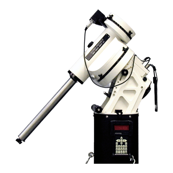
- Page 1 ASTRO-PHYSICS 1200 GERMAN EQUATORIAL WITH GTO SERVO MOTOR DRIVE Model GTOCP3 ASTRO-PHYSICS, INC 11250 Forest Hills Road Rockford, IL 61115 Telephone: (815)-282-1513 Fax: (815)-282-9847 support@astro-physics.com www.astro-physics.com February 8, 2005...
-
Page 3: Table Of Contents
ASTRO-PHYSICS 1200 GERMAN EQUATORIAL WITH GTO SERVO MOTOR DRIVE MODEL 1200GTO PARTS LIST – MODEL GTOCP3 FEATURES AND SPECIFICATIONS INTRODUCTION Why Polar Alignment is Important Compensation for the Earth’s rotation ASSEMBLY DIAGRAM BEFORE YOU LEAVE HOME BEFORE YOU LEAVE HOME... - Page 4 RETICLE Connector AUTOGUIDER Connector +6V Connector N and S Switch Removing the GTO Control Box From 1200 Mount GTO KEYPAD OPERATION PULSEGUIDE BY SIRIUS-IMAGING CABLE MANAGEMENT 1200 Motor Cables Accessory Cables Example from International Space Station – Amateur Telescope (ISS-AT) Project SLEWING YOUR MOUNT IN BELOW FREEZING TEMPERATURES MOUNT CARE AND ALIGNMENT Mount Maintenance...
-
Page 5: Model 1200Gto Parts List - Model Gtocp3
GTO SERVO MOTOR DRIVE MODEL 1200GTO PARTS LIST – MODEL GTOCP3 Polar axis assembly (right ascension-R.A.) with Servo Box GTOCP3 Declination (Dec.) axis assembly 18.5” Stainless counterweight shaft (1.875” dia.) with washer stop and black plastic knob (knob has 5/16 thread) Y cable –... -
Page 6: Introduction
INTRODUCTION The 1200 German equatorial was designed to meet the needs of the advanced observer who requires a mount with maximum strength and rigidity and minimum weight. The excess material in both axes has been carved out while retaining a heavily ribbed structure for internal strength and rigidity. -
Page 7: Assembly Diagram
ASSEMBLY DIAGRAM Please read all instructions before attempting to set up your 1200 mount. The Model 1200 is very rugged, however like any precision instrument, it can be damaged by improper use and handling. Please refer to Diagram 2 for an illustration of the mount. -
Page 8: Before You Leave Home
BEFORE YOU LEAVE HOME Since most of us must set up our instruments in the dark, in the cold or while battling mosquitoes, a bit of pre-planning and organization is important. There are few simple things that can be accomplished in the comfort of your home before heading outside. -
Page 9: Attach Pier Adapter To Pier Post (Purchased Separately)
Attach Pier Adapter to Pier Post (purchased separately) If you purchased the pier from Astro-Physics, the pier adapter of the 1200 may be already attached to the top of the pier. If you are constructing your own pier or tripod, you will need to incorporate this part. Two models of the pier adapter are now available for use with the 1200 from Astro-Physics. -
Page 10: At Your Observing Site
AT YOUR OBSERVING SITE Assemble Pier (purchased separately) Begin by assembling the portable pier at the desired observing location. Take note which direction is north. Slide the three legs onto the nubs of the base and rotate the assembly so that one of the legs points toward north (or south, if that is your preference). -
Page 11: Fine Polar Alignment
If you examine the polar axis assembly, you will see that the center of the R.A. shaft is hollow. NOTE: If you have already attached the Dec. axis, remove the sight hole cover and rotate the internal Dec. shaft by moving the top of the Dec. -
Page 12: Azimuth Adjustments
• Members of the ap-gto Yahoo group occasionally discuss alternative methods of polar alignment that they have found helpful. We suggest that you participate in this Internet discussion group. Follow the links from the sidebar of our website to find the group. Azimuth Adjustments The one-piece Azimuth Adjustment assembly makes for easy and accurate polar alignment in your observatory or in the field. -
Page 13: Tips For Adjusting The Altitude
parts. It is also possible to make fine altitude adjustments by using the turnbuckle on the north leg of our pier, if used. One turn of the altitude knob is approximately 0.5 degrees (30 arc minutes). Tips for Adjusting the Altitude The mount's polar axis is held in place between the two side plates. -
Page 14: Assemble Declination Axis
Assemble Declination Axis Do not have your telescope or counterweights connected to the Dec. axis assembly for either assembly or disassembly of the Dec. and RA axes. Position the R.A. axis as shown in Diagram 7 with the pocket "A" at the top, opposite the altitude adjuster knob. Firmly tighten R.A. -
Page 15: Attach Mounting Plate (Purchased Separately)
Attach this plate with six 1/4-20 x1" socket head cap screws. 8.5” DOVETAIL FOR LOSMANDY D SERIES PLATE (DOVELM2) This Astro-Physics plate attaches to the 400, 600E, 900 and 1200 mounts. If you already own one of the Losmandy DAP series (fits Astro-Physics refractors), DC series (for Celestron 8", 11"... -
Page 16: Understanding The R.a. And Dec. Clutch Knobs
If you find that you are no longer able to adjust the tension and the knobs are locked firmly in place so that the axis will not move, contact Astro-Physics for technical assistance. Attach Counterweight Shaft and Counterweights IMPORTANT: •... -
Page 17: Attach Mounting Rings And Scope (Purchased Separately)
Attach Mounting Rings and Scope (purchased separately) Flat and ribbed plates: Our flat and ribbed plates are constructed with keyhole slots at the location where your mounting rings attach. This feature enables you to partially loosen the screws on your rings just enough to insert them into the larger part of the keyhole, then slide the rings to the narrow part and tighten them with a hex key. -
Page 18: Servo Motor Drive
SERVO MOTOR DRIVE GTO Control Box – Model GTOCP3 The GTO control box contains all of the circuitry to drive the two servo motors and the logic required to navigate the sky. It will be operational and track at the sidereal rate when connected to both motors of the mount and a power source. In order to control the movement of the mount, you will need to connect at least one of these: •... -
Page 19: Power Indicator Light
POWER Indicator Light This LED will remain illuminated when your power source has sufficient output to drive the motors. If the voltage falls below 10.5 volts, the power light will go out and the motors will stop. The keypad will not function properly. For mounts shipped after 02-25-00: If the LED turns yellow, this means that your motors are overloaded, probably due to an unbalanced load on your mount. -
Page 20: N And S Switch
N and S Switch Select northern (N) or southern (S) hemisphere as needed. When you slide the switch to the opposite position, the tracking direction of the drive will reverse. The power cord must be removed and re-attached to make this work. Removing the GTO Control Box From 1200 Mount The GTO control box can be removed easily from the RA axis. -
Page 21: Cable Management
CABLE MANAGEMENT The movement of the mount across the meridian during slewing functions is calculated so that the cables will not tangle if they are set up properly. In addition to the motor and power cables that are provided with the mount, you may have additional cables for other accessories. - Page 22 Allen head bolts. This allowed the Dec cable to slide easily over the axis in all orientations and there was no snagging of the wire anywhere. Please call Astro-Physics if you would like to order these bolts. Do not try to install normal Allen...
-
Page 23: Slewing Your Mount In Below Freezing Temperatures
SLEWING YOUR MOUNT IN BELOW FREEZING TEMPERATURES Notes from Roland during a very cold spell in January 2005: “There are several potential problems when slewing your mount in below freezing temperatures. The symptoms are a wavering or chattering sound from the motors, a slowing down of the slewing with a sudden jolting stop at the end of the slew, and in the worst case, a continuous running of the motors and loss of control. -
Page 24: Mount Care And Alignment
Once out of the hole, you can either sand the outside down with a bit of emery paper until it goes smoothly into the threaded hole in the Dec axis, or call Astro-Physics, and we can send you 4 new ones (or 8, if both axes are involved). Replacement with new ones is the preferred solution, however sanding them down may get you up and running quickly. - Page 25 Just remove the cover on the gearbox and add the oil drops. The noise is nothing to worry about. Refer the section of this manual entitled: Slewing Your Mount in Below Freezing Temperatures. If any problems occur, please don't hesitate to contact Astro-Physics for assistance. ASTRO-PHYSICS INC 11250 Forest Hills Road Rockford, IL 61115...
-
Page 26: Installation Of Encoders And Encoder Housings -1200 Mount
INSTALLATION OF ENCODERS AND ENCODER HOUSINGS -1200 MOUNT 1200ENC (purchased separately) Parts List: Right Ascension (R.A.) Encoder housing (black anodized) Declination (Dec.) Encoder housing (black anodized) R.A. Axis Adapter (clear anodized - silver colored), labeled R.A. Dec. Axis Adapter (clear anodized - silver colored), labeled Dec. To install your encoders, first remove the telescope from your mount. -
Page 27: Fitting Right Ascension Encoder Housing
Fitting Right Ascension Encoder Housing If the encoders were purchased with the 1200 mount, it is likely that the right ascension axis adapter and encoder housing have already been installed. Please continue to read these directions since you may need to remove and reinstall the encoders if you use a polar alignment scope.
Need help?
Do you have a question about the GTOCP3 and is the answer not in the manual?
Questions and answers