Table of Contents
Advertisement
Quick Links
Advertisement
Table of Contents

Summary of Contents for CENTRAL RESTAURANT PRODUCTS 69K-102
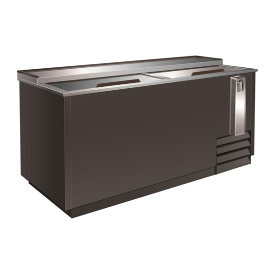
- Page 1 BOTTLE COOLER Service, Installation and Care Manual Please read this manual completely before attempting to install or operate this equipment. Notify carrier of damage! Inspect all components immediately. See page 2. IMPORTANT INFORMATION READ BEFORE USE PLEASE SAVE THESE INSTRUCTIONS!
-
Page 2: Table Of Contents
115/60/1 3200 10.6 5-15P 69K-101 115/60/1 5400 11.3 5-15P 69K-102 115/60/1 7600 12.0 5-15P CONGRATULATIONS ON YOUR NEW COOLER Note these instructions apply to all coolers. Installations of equipment may not exactly correspond to your model. INSTALLATION Make sure that the cooler is not damaged on arrival. Your supplier must be notified of any transport damage, within 24 hours of delivery. -
Page 3: Electrical Connection
Service and Installation Manual ELECTRICAL CONNECTION The cooler must be connected to a socket with the correct voltage/frequency, as show on the nameplate. The standard for u.s is 115V/50HZ. Voltage variations of ±10% are acceptable. Greater variations can damage the cooler, and in such cases the factory warranty is not valid. In the case of extreme voltage variation, above or below the standard, your local supplier will be able to advise you, what to do. - Page 4 Service and Installation Manual OPERATION Do not throw items into the storage area. Failure to heed these recommendations could result in damage to the interior of the cabinet. Refrigerated cycle Refrigerators: During the refrigeration cycle, the evaporator fans wilt run continuously even when one or more doors are open.
- Page 5 Service and Installation Manual 2. MAIN FUNCTIONS 2.1 HOW TO SEE THE SETPOINT 1. Push and immediately release the SET key: the display will show the set point value. 2. Push and immediately release the SET key or wait for 5 seconds to display the sensor value again.
-
Page 6: Maintenance
Service and Installation Manual MAINTENANCE This cooler can be cleaned using warm water and a mild detergent. Rinse with clean water to finish off. Never use detergents that contain chlorine. The lid may be cleaned in the same way as the cooler. If a condenser and associated fan are fitted at the back bottom of the cooler, they can gather dust and dirt. -
Page 7: Wiring Diagram
Service and Installation Manual WIRING DIAGRAM MODEL:69K-100/69K-101 MODEL:69K-102... - Page 8 Service and Installation Manual WIRING DIAGRAM MODEL: 69K-100/69K-101...
- Page 9 Service and Installation Manual WIRING DIAGRAM MODEL: 69K-102...
Need help?
Do you have a question about the 69K-102 and is the answer not in the manual?
Questions and answers