Table of Contents
Advertisement
Quick Links
Advertisement
Table of Contents

Related Manuals for Apogee Instruments SQ-646


Summary of Contents for Apogee Instruments SQ-646
-
Page 1: Owner's Manual
OWNER’S MANUAL QUANTUM LIGHT POLLUTION SENSOR Model SQ-646 Rev: 4-Oct-2021 APOGEE INSTRUMENTS, INC. | 721 WEST 1800 NORTH, LOGAN, UTAH 84321, USA TEL: (435) 792-4700 | FAX: (435) 787-8268 | WEB: APOGEEINSTRUMENTS.COM Copyright © 2021 Apogee Instrument, Inc. -
Page 2: Table Of Contents
TABLE OF CONTENTS Owner’s Manual ....................................1 Certificate of Compliance ................................3 Introduction....................................4 Sensor Models ....................................5 Specifications....................................6 Deployment and Installation ................................ 8 Software Installation ..................................9 Operation and Measurement ..............................10 Windows Software ..................................11 Mac Software ..................................... 16 Maintenance and Recalibration .............................. -
Page 3: Certificate Of Compliance
RoHS 3 compliant using exemption 6c. Further note that Apogee Instruments does not specifically run any analysis on our raw materials or end products for the presence of these substances, but we rely on the information provided to us by our material suppliers. -
Page 4: Introduction
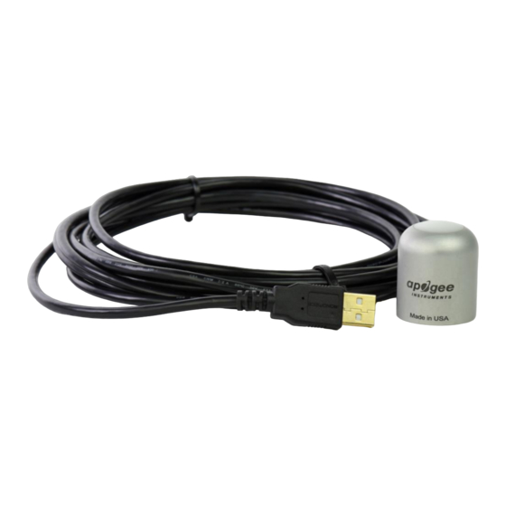
This means this particular sensor should only be used for photon flux density measurements under LEDs. Apogee Instruments SQ-600 series Quantum Light Pollution Sensors consist of a cast acrylic diffuser (filter), photodiode, and signal processing circuitry mounted in an anodized aluminum housing, and a cable to connect the sensor to a measurement device. -
Page 5: Sensor Models
SENSOR MODELS This manual covers the USB Quantum Light Pollution sensor, model SQ-646 (listed in bold below). Additional models are covered in their respective manuals. Model Signal SQ-640 Self-powered SQ-642 0-2.5 V SQ-644 4-20 mA SQ-645 0-5 V SQ-646 SQ-647... -
Page 6: Specifications
61 mA Calibration Traceability Apogee Instruments SQ-600 series quantum light pollution sensors are calibrated through side-by-side comparison to the mean of four transfer standard quantum light pollution sensors under a reference lamp. The transfer standard quantum light pollution sensors are recalibrated with a quartz halogen lamp traceable to the National... - Page 7 Spectral Response Mean spectral response measurements of Mean spectral response measurements of Mean spectral response measurements of six six replicate Apogee SQ-600 series Extended six replicate Apogee SQ-600 series Quantum replicate Apogee SQ-100 (original) and SQ- Range PFD Sensors. Spectral response Light Pollution Sensors.
-
Page 8: Deployment And Installation
An Apogee Instruments model AL-100 leveling plate is recommended for this purpose. To facilitate mounting on a cross arm, an Apogee Instruments model AL- 120 mounting bracket is recommended. -
Page 9: Software Installation
SOFTWARE INSTALLATION The most recent version of ApogeeConnect software can be downloaded at http://www.apogeeinstruments.com/downloads/. Installing the software on a PC (Windows compatible, XP and later) 1. Double click on the installer package: 2. On the ‘Welcome’ screen, please click ‘Next’ to continue. 3. -
Page 10: Operation And Measurement
OPERATION AND MEASUREMENT Low Light Measurements Accurate low light measurements are required in flowering and light pollution studies. Research indicates flowering can be triggered in some plants at photosynthetic and/or far-red photon flux densities less than 0.1 mol . The threshold photon flux density at which flowering is triggered is variable among species. Two of the most light-sensitive species are Poinsettias and Cannabis. -
Page 11: Windows Software
WINDOWS SOFTWARE When the SQ-646 sensor is not plugged into the USB port, the software will display a message in the lower left corner, “Device Not Connected,” indicating it cannot establish communication with the sensor. Plug the sensor into a USB port and allow some time for the sensor to automatically establish communication with the software. - Page 12 Click the ‘Settings’ icon to display the software options. Note ‘Light Source’ is not a selectable option. This function is not necessary for the SQ-646. The function is designed to give increased accuracy for the SQ-420. Note the ‘Immersion Setting’ function is not necessary for the SQ-646.
- Page 13 After clicking the ‘Recalibate’ button the user will be prompted to cover the sensor. Place a dark cap over the sensor and wait for the real-time PFD reading to settle at zero. Click OK. Uncover the sensor and wait for the PFD reading to settle before entering the reference value.
- Page 14 These can be used to help troubleshoot if problems arise. ‘Manage Field Logging’ is used to setup the SQ-646 for use in the field. When the SQ-646 is supplied power from a USB power source (plug or select batteries) it will log data which you can retrieve.
- Page 15 To use additional SQ-646 devices, open additional SQ-646 software windows. The device serial number will display in the lower left-hand corner of the corresponding software window. Devices may be selected by serial...
-
Page 16: Mac Software
MAC SOFTWARE When the SQ-646 sensor is not plugged into the USB port, the software will display a message in the lower left corner, “Device Not Connected,” indicating it cannot establish communication with the sensor. Plug the sensor into a USB port and allow some time for the sensor to automatically establish communication with the software. - Page 17 Click the ‘Settings’ icon to display the software options. Note the ‘Light Source’ function is not necessary for the SQ-646. The function is designed to give increased accuracy for the SQ-420. Note the ‘Immersion Setting’ function is not necessary for the SQ-646. This function automatically applies the SQ-520 immersion effect correction factor of 1.32 to...
- Page 18 Clicking ‘Calibration’ will display the factory calibrated multiplier and offset values. These values are saved in firmware and can be recovered by clicking the ‘Recover Original’ button. Deriving a new calibration multiplier and offset is accomplished by clicking the ‘Recalibrate’ button. This is applicable if users want to calibrate the sensor to their own specific light source.
- Page 19 Clicking ‘Data Logging’ will allow the user to log interval measurements in a csv file while the software is open and communicating with the sensor. Click ‘Setup’ and the Setup Logging window appears. Click the ‘Browse button to create or select a csv file. Select the desired sampling interval.
- Page 20 ‘Manage Field Logging’ is used to setup the SQ-626 for the use in the field. When the SQ-626 is supplied power from a USB power source (plug or select batteries) it will log data which you can retrieve. Choose the interval the data is saved, as well as the interval that data is sampled and the light source used.
- Page 21 To use additional SQ-646 devices, open additional SQ-646 software windows. The device serial number will display in the lower left-hand corner of the corresponding software window. Devices may be selected by serial...
-
Page 22: Maintenance And Recalibration
3. Salt deposit accumulation from evaporation of sea spray or sprinkler irrigation water. Apogee Instruments upward-looking sensors have a domed diffuser and housing for improved self-cleaning from rainfall, but active cleaning may be necessary. Dust or organic deposits are best removed using water, or window cleaner, and a soft cloth or cotton swab. -
Page 23: Troubleshooting And Customer Support
TROUBLESHOOTING AND CUSTOMER SUPPORT Cable Length Fifteen feet is the maximum cable length that can be built into the sensor. Modifying Cable Length If you required a longer cable length an “active” USB extension cable is required. Please note, the connection between the cables must be made watertight prior to submersion. -
Page 24: Return And Warranty Policy
RETURN AND WARRANTY POLICY RETURN POLICY Apogee Instruments will accept returns within 30 days of purchase as long as the product is in new condition (to be determined by Apogee). Returns are subject to a 10 % restocking fee. WARRANTY POLICY... - Page 25 84321, USA 5. Upon receipt, Apogee Instruments will determine the cause of failure. If the product is found to be defective in terms of operation to the published specifications due to a failure of product materials or craftsmanship, Apogee Instruments will repair or replace the items free of charge.
Need help?
Do you have a question about the SQ-646 and is the answer not in the manual?
Questions and answers