
Related Manuals for DATATEC R&S NGL Series

Summary of Contents for DATATEC R&S NGL Series
- Page 1 ® R&S NGL200/NGM200 Power Supply Series Getting Started (;ÜåD2) 1178872002 Version 06 Distributed by: Sie haben Fragen oder wünschen eine Beratung? Angebotsanfrage unter 07121 / 51 50 50 oder über info@datatec.de...
- Page 2 ® This manual describes the following R&S NGL/NGM models with firmware ver- sion 1.00 and higher: ● R&S ® NGL201 Single-channel power supply 60W (3638.3376.02) ● R&S ® NGL202 Two-channel power supply 120W (3638.3376.03) ● R&S ® NGM201 Single-channel power supply 60W (3638.4472.02) ●...
- Page 3 Safety Instructions Instrucciones de seguridad Sicherheitshinweise Consignes de sécurité Risk of injury and instrument damage The instrument must be used in an appropriate manner to prevent electric shock, fire, personal injury or instrument damage. ● Do not open the instrument casing. ●...
- Page 4 Gefahr von Verletzungen und Schäden am Gerät Betreiben Sie das Gerät immer ordnungsgemäß, um elektrischen Schlag, Brand, Verletzungen von Personen oder Geräteschäden zu verhindern. ● Öffnen Sie das Gerätegehäuse nicht. ● Lesen und beachten Sie die "Grundlegenden Sicherheitshinweise", die als gedruckte Broschüre dem Gerät beiliegen.
-
Page 5: Table Of Contents
® Contents R&S NGL200/NGM200 Contents 1 Documentation Overview............5 1.1 Manuals....................5 1.2 Data Sheet..................... 6 1.3 Release Notes, Open Source Acknowledgment........ 6 1.4 Application Notes, Application Cards, Videos........6 2 Welcome to R&S NGL/NGM..........7 3 Putting into Operation............9 3.1 Safety....................11 3.2 Intended Operation................ - Page 6 ® Contents R&S NGL200/NGM200 6.1 Maintenance..................26 6.2 Contacting Customer Support............26 Index..................28 Getting Started 1178.8720.02 ─ 06...
-
Page 7: Documentation Overview
® Documentation Overview R&S NGL200/NGM200 Manuals Documentation Overview This section provides an overview of the R&S NGL/NGM user documentation. Manuals You find the documents on the R&S NGL/NGM product page at: www.rohde-schwarz.com/product/ngl200 www.rohde-schwarz.com/product/ngm200 Getting Started Introduces the R&S NGL/NGM power supply series and describes how to set up and start working with the instrument. -
Page 8: Data Sheet
® Documentation Overview R&S NGL200/NGM200 Application Notes, Application Cards, Videos and contains mechanical drawings and spare part lists. The service manual is available for registered users on the global Rohde & Schwarz information system (GLORIS, https://gloris.rohde-schwarz.com). Data Sheet The datasheet contains the technical specifications of the R&S NGL/NGM power supply series. -
Page 9: Welcome To R&S Ngl/Ngm
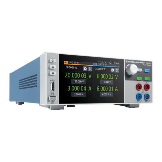
® Welcome to R&S NGL/NGM R&S NGL200/NGM200 Welcome to R&S NGL/NGM The one or two-channel power supply series are based on a classical transformer concept with linear regulators. This concept allows the instrument to achieve highest accuracy and lowest residual ripple. The R&S NGL/NGM power supply series feature galvanically isolated, floating overload and short-circuit proof outputs. - Page 10 ® Welcome to R&S NGL/NGM R&S NGL200/NGM200 (http://www.rohde-schwarz.com/product/ngl200 for R&S NGL and http:// www.rohde-schwarz.com/product/ngm200 for R&S NGM) . Getting Started 1178.8720.02 ─ 06...
-
Page 11: Putting Into Operation
® Putting into Operation R&S NGL200/NGM200 Putting into Operation This chapter describes how to set up the R&S NGL/NGM power supply series for the first time. Risk of injury due to disregarding safety information Observe the information on appropriate operating conditions provided in the data sheet to prevent personal injury or damage to the instrument. - Page 12 ® Putting into Operation R&S NGL200/NGM200 Risk of radio interference This instrument is compliant with Class A of CISPR 32. In a residential envi- ronment, this instrument may cause radio interference. Risk of instrument damage during operation An unsuitable operating site or test setup can cause damage to the instru- ment and the connected devices.
-
Page 13: Safety
® Putting into Operation R&S NGL200/NGM200 Safety Safety Recommendations on secure operation The R&S NGL/NGM is designed to operate at local workplaces or in secured networks (LAN). It should not be accessible from the internet, because of a potential security risk, e.g. attackers could misuse or damage your device. -
Page 14: Intended Operation
® Putting into Operation R&S NGL200/NGM200 Intended Operation Risk of electric shock It is prohibited to disconnect the earthed protective connection inside or out- side of the instrument! If it is assumed that a safe operation is no longer possible, the instrument must be shut down and secured against any unintended operation. - Page 15 ® Putting into Operation R&S NGL200/NGM200 Intended Operation Use only the power cable included in the delivery package. See "Delivery package" on page 15. Before each measurement, measuring cables must be inspected for dam- age and replaced if necessary. Damaged or worn components can damage the instrument or cause injury.
-
Page 16: Unpacking And Checking The Instrument
® Putting into Operation R&S NGL200/NGM200 Unpacking and Checking the Instrument General data Weight R&S NGL201 7.1 kg (15.65 lb) R&S NGM201 7.2 kg (15.87 lb) R&S NGL202 7.3 kg (16.09 lb) R&S NGM202 7.4 kg (16.31 lb) Unpacking and Checking the Instrument Unpack the R&S NGL/NGM power supply carefully and check the content of the package. -
Page 17: Setting Up The Instrument
® Putting into Operation R&S NGL200/NGM200 Setting Up the Instrument Delivery package The package contents contain the following items: ● R&S NGL power supply or R&S NGM power supply ● Four power cables ● One printed Getting Started manual ● One document folder containing a printed Basic Safety Instructions guide Setting Up the Instrument The R&S NGL/NGM is designed for benchtop and rackmount operation. -
Page 18: Rack Mounting
® Putting into Operation R&S NGL200/NGM200 Setting Up the Instrument 3.4.2 Rack Mounting The instrument can be installed in a 19" rack using the rack adapter R&S HZN96 (P/N 3638.7813.02). Proceed according to the installation instructions supplied with the rack adapter. Ambient temperature Place the R&S NGL/NGM power supply in an area where the ambient tem- perature is within +5 °C to +40 °C. -
Page 19: Instrument Tour
® Instrument Tour R&S NGL200/NGM200 Overview of Controls Instrument Tour This chapter provides an overview of all the controls available in the R&S NGL/NGM models and steps to switch on the instrument for the first time. ● Overview of Controls..................17 ●... - Page 20 ® Instrument Tour R&S NGL200/NGM200 Overview of Controls 5 = Output terminals (one channel with sense for NGL201, NGM201; two channels for NGL202, NGM202) 6 = USB connector 7 = Power key Display (1) The display is a color TFT touch screen. Depending on the instrument model, up to two channels are shown on the display.
-
Page 21: Rear Panel
® Instrument Tour R&S NGL200/NGM200 Overview of Controls Both instrument models are equipped with 4 terminals. The NGL201, NGM201 models provide both the output plus the sense connectors at the front panel while the NGL202, NGM202 models provide only output terminals for both channels. USB connector (6) The USB connector is a Type-A connector. - Page 22 ® Instrument Tour R&S NGL200/NGM200 Overview of Controls AC inlet with fuse holder and voltage selector (8) Main supply cord Do not use detachable mains supply cord with inadequate rating. The power cable must be plugged in before signal circuits can be connected. Do not use the product if the power cable is damaged.
- Page 23 ® Instrument Tour R&S NGL200/NGM200 Overview of Controls Ethernet connector (13) 10/100 Ethernet port for remote control operation via the local area network. For a detailed description on the connection setup, see section "LAN Connection" in the User Manual. Option IEEE-488 (GPIB) interface (14) An IEEE-488 (GPIB) interface can be ordered (NGL-B105 or NGM-B105).
-
Page 24: Switching On The Instrument
® Instrument Tour R&S NGL200/NGM200 Switching On the Instrument Table 4-2: Inhibit signals Signal name Descriptions Inhibit Ch1 Pin 1 of Digital I/O If the inhibit signal goes active, channel 1 connector output is turned off. The inhibit signal is low active (inverted logic). - Page 25 ® Instrument Tour R&S NGL200/NGM200 Switching On the Instrument 2. Connect the power cable to the socket outlet. 3. Press [Power] key on the front panel. The instrument performs a system check, boots the operating system, and starts the R&S NGL/NGM firmware. By default, all output channels are turned off when the instrument is switched on to prevent connected loads from being damaged unintentionally.
-
Page 26: Trying Out The Instrument
® Trying Out the Instrument R&S NGL200/NGM200 Activating the Channels Output Trying Out the Instrument This chapter describes some basic functions that you can perform with the R&S NGL/NGM. Source and sink current The R&S NGL/NGM power supply series are 2 quadrant power supplies which may both source and sink current. - Page 27 ® Trying Out the Instrument R&S NGL200/NGM200 Activating the Channels Output To switch on or off channel output. 1. For the two-channel models, select desired channel key ([Ch1] or [Ch2]) on the front panel. 2. Press [Output] key. The R&S NGL/NGM outputs the set voltage level on the output channel termi- nal.
-
Page 28: Maintenance And Support
® Maintenance and Support R&S NGL200/NGM200 Contacting Customer Support Maintenance and Support Maintenance Regular maintenance improves the life span of the instrument, the following chap- ter provides information on instrument maintenance. Cleaning Before cleaning the instrument, ensure that it has been switched off and the power cable is disconnected. - Page 29 ® Maintenance and Support R&S NGL200/NGM200 Contacting Customer Support Contact information Contact our customer support center at www.rohde-schwarz.com/support, or fol- low this QR code: Figure 6-1: QR code to the Rohde & Schwarz support page Getting Started 1178.8720.02 ─ 06...
- Page 30 Open source acknowledgment (OSA) ..6 Overview of controls Front panel ..........17 Rear panel .......... 19 Getting Started 1178.8720.02 ─ 06 Distributed by: Sie haben Fragen oder wünschen eine Beratung? Angebotsanfrage unter 07121 / 51 50 50 oder über info@datatec.de...
Need help?
Do you have a question about the R&S NGL Series and is the answer not in the manual?
Questions and answers