
Related Manuals for Advanced Electronics MxPro5

Summary of Contents for Advanced Electronics MxPro5
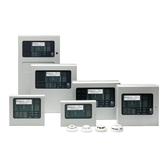
- Page 1 www.acornfiresecurity.com Fire Alarm Panels User Manual The operation and functions described in this manual are available from Software Version 5000-050-04 onwards. www.acornfiresecurity.com...
- Page 2 www.acornfiresecurity.com This page is intentionally blank www.acornfiresecurity.com...
-
Page 3: Table Of Contents
www.acornfiresecurity.com Table of Contents Page INTRODUCTION............................. 5 ............................. 5 TANDARDS ........................6 AUTIONS AND ARNINGS ............................6 ESCRIPTION 1.3.1 5000 Series ............................6 1.3.2 5000V Series............................6 1.3.3 5000N Series ............................. 6 CONTROLS AND INDICATIONS........................7 ..........................7 RAPHICAL ISPLAY LED S ........................ - Page 4 www.acornfiresecurity.com 3.10.2.4 Fire Protection Outputs .......................... 27 3.10.2.5 Fault Routing Outputs..........................28 3.10.2.6 All Other Relay Outputs ......................... 28 3.10.2.7 Selected Outputs ........................... 28 3.10.2.8 Pager ..............................28 3.10.2.9 Only Selected Outputs ........................... 28 3.10.3 Disable - Controls ........................28 Disable –...
-
Page 5: Introduction
1 Introduction Standards Advanced Electronics Ltd declares that the products identified below conform to the essential requirements specified in the Construction Products Directive 89/106/EEC: 0786-CPD-20952 EN54-2: 1997 +A1:2006 Control and indicating equipment for fire detection and fire alarm systems for buildings... -
Page 6: Cautions And Warnings
www.acornfiresecurity.com Cautions and Warnings BEFORE INSTALLATION – Refer To the Ratings shown on the label inside the product and to the ‘Specifications Chart’ in this document. Please read this manual carefully. If you are unclear on any point DO STOP NOT proceed. -
Page 7: Controls And Indications
www.acornfiresecurity.com 2 Controls and Indications The 5000, 5000V and 5000N series are provided with indications and control functions as shown in the diagram below and described in the following text. The LED functions and BUTTON functions may be assigned and used differently in specific countries dependent on the market and standards requirements. -
Page 8: Led Status Indicators
www.acornfiresecurity.com LED Status Indicators The LED Status Indications show the basic operational state of the panel and whether the panel is in a fire alarm, fault, disabled or test condition. Function Colour Description FIRE Indicates that the system has detected a fire alarm condition MORE ALARMS Indicates that the system has detected a fire alarm condition (on steady) in more than one zone. -
Page 9: Control Buttons
www.acornfiresecurity.com Control Buttons The following table contains a list of all of the control button functions available. The buttons available on each product depend on the country of installation and specific market requirements. Button Description Access Level More Alarms Available in both Press to scroll through Zones in Alarm. -
Page 10: Number And Letter Buttons
www.acornfiresecurity.com Number and Letter Buttons A B C D E F G H I J K L M N O Used to enter numbers or letters. P Q R S T U V W X Y Z E S C M E N U Press to return to a previous menu. -
Page 11: Changing From Access Level 1 To Level 2
www.acornfiresecurity.com 3.1.1 Changing from Access Level 1 to Level 2 If the panel has an access key switch fitted, use the key in preference to the menu options shown below. 3.1.1.1 Menu Access Press the ‘MENU’ button. The level 1 menu will be displayed as shown below: [ CONTROLS DISABLED ] ENABLE CONTROLS VIEW... -
Page 12: Fire Alarm Condition
www.acornfiresecurity.com Fire Alarm Condition When the system registers a fire alarm condition the Red Fire Indicator illuminates, the internal buzzer sounds (continuously) and the display shows the zone in which the fire originated. The sounders, relays and other outputs will be turned on depending on the programming in the panel. An example of the display is shown below: - <... -
Page 13: Detailed Fire Alarm Information
www.acornfiresecurity.com 3.2.1 Detailed Fire Alarm Information Press the ‘MORE ALARMS’ button to view the list of zones in a fire alarm condition. Press the ‘MORE ALARMS’ button again or use the buttons to scroll through the list. Each press highlights the next zone in the list and scrolls the zone list upwards. -
Page 14: Fault Condition
www.acornfiresecurity.com Note: The EVACUATION button will terminate the investigation delays and activate all programmed sounders. Fault Condition When the system registers a fault condition the Yellow Fault Indicator is illuminated, the internal buzzer sounds intermittently and the display shows the cause of the fault in more detail. An example of the display is shown below: ZONE 0001 DEVICE MISSING... -
Page 15: Disablement Condition
www.acornfiresecurity.com Disablement Condition If any zones, input devices or output devices have been disabled, the DISABLE Indicator is illuminated. In addition, the SOUNDER DISABLE Indicator is illuminated if one or more sounder circuits or devices have been disabled. The display indicates the presence of zone disablement conditions in the lower half of the display as follows: LEVEL 2 16:05... -
Page 16: Disabled Outputs
www.acornfiresecurity.com 3.4.2 Disabled Outputs The display presents a list of all of the zones in a disabled condition with the first disablement highlighted. For example: [ 2 Zone(s)with Outputs Disabled] More> Zone Mode Location 0001 ALL DISABLED BASEMENT WEST < Zones with location text where 0100 ALL DISABLED RECEPTION <... -
Page 17: Supervisory Condition
www.acornfiresecurity.com Supervisory Condition When the system registers a supervisory condition, the internal buzzer sounds intermittently and the display shows the cause of the fault in more detail. An example of the display is shown below: ZONE 0011 SUPERVISORY PLANT ROOM <... - Page 18 www.acornfiresecurity.com Main Menu Option Sub Menus Comments Fires View Zones and Inputs that are reporting a fire alarm condition. VIEW Faults View Zones and Inputs that are reporting a fault condition. Alarms View Zones and Inputs that are reporting an alarm condition. Disabled View Zones, Inputs and Outputs that are disabled.
-
Page 19: Using The Buttons To Navigate Menus
www.acornfiresecurity.com 3.8.1 Using the Buttons to Navigate Menus Press the ‘Menu’ button to bring up the display menu. 3.8.1.1 Selecting Menu Options The Level 2 Menu is shown below: [Level 2 Menu] User 1 Node VIEW DISABLE ENABLE TEST DELAY TOOLS STATUS Press the ... -
Page 20: Viewing
www.acornfiresecurity.com Viewing The View menu is available on two pages. Highlight the “Next Menu” option and pres the ✔ button to select the next page. [View Menu 1] User 1 Node FIRES FAULTS ALARMS DISABLED INPUTS OUTPUTS Next Menu [View Menu 2] User 1 Node PANEL NETWORK... -
Page 21: View - Inputs
www.acornfiresecurity.com 3.9.5 View - Inputs This function shows the current operational condition for all Zones and Individual Inputs. The display presents a list of all of the zones containing input devices, with the first zone highlighted. For example: [Inputs] More> Zone Mode Location 0001 Enabled... -
Page 22: View - Panel
www.acornfiresecurity.com 3.9.7 View - Panel The View Panel Option provides three items to view diagnostic on the panel. [Panel Information] LOCAL-HARDWARE SOFTWARE NETWORK-HARDWARE Press the buttons to highlight the required menu option and then press the ✔ button to select it. ... -
Page 23: Local Hardware
www.acornfiresecurity.com 3.9.7.2 Local Hardware The Local Hardware Option provides a diagnostic readout of the operational condition and readings for the internal panel electronic circuits of this panel. When the option is selected, the display shows a list of the circuits. For example: [Panel Circuits] DESCRIPTION VALUE... -
Page 24: Network Hardware
www.acornfiresecurity.com 3.9.7.3 Network Hardware The Network Hardware Option provides a diagnostic readout of the operational condition and readings for the internal panel electronic circuits of other nodes / panels on the network. When the option is selected, the display shows a list of the nodes indexed by their assigned zone number. For example: [HARDWARE] More>... -
Page 25: Alarm Counter
www.acornfiresecurity.com 3.9.8.2 Alarm Counter Alarm Counter. The Panel records the number of times that the fire alarm condition has occurred at the panel. Section 7.13 [View Alarm Counter] 0000000033 In the above example, the panel has entered the fire alarm condition 33 times since it was installed. The panel increments the count by one each time it changes from the normal condition to indicate a fire alarm condition. -
Page 26: Disabling
www.acornfiresecurity.com 3.10 Disabling On selecting the Disable Menu, the display shows five possible options. For example: [Disable] User 1 Node ZONE/INPUTS OUTPUTS GROUPS CONTROLS USER-ID Press the buttons to highlight the required menu option and then press the ✔ button to select it. 3.10.1 Disable - Zones and Inputs This option provides the means to disable a complete zone, disable all input devices except call points or disable individual input devices. -
Page 27: Disable - Outputs
www.acornfiresecurity.com If ONLY AUTOMATIC DETECTORS is chosen, the pop-up window disappears and the State of the Zone is changed to PART DISABLED. Smoke and heat detectors are disabled. If ONLY MANUAL DEVICES is chosen, the pop-up window disappears and the State of the Zone is changed to PART DISABLED. -
Page 28: Fault Routing Outputs
www.acornfiresecurity.com 3.10.2.5 Fault Routing Outputs Press the buttons to scroll through and highlight the FAULT ROUTING OUTPUT Option and then press the ✔ button to disable all fault routing outputs. The display automatically reverts to the Main Disable Menu. 3.10.2.6 All Other Relay Outputs Press the ... -
Page 29: Disable - User Id
www.acornfiresecurity.com 3.10.4 Disable – User ID This operation will cancel the current User ID and return to the default User 1. User 1 can perform all actions except those defined as programmable (refer to the menu table). [Disable] User 5 Node ZONE/INPUTS OUTPUTS GROUPS... -
Page 30: Enabling
www.acornfiresecurity.com 3.11 Enabling On selection of the Enable Menu Option, the display shows the available Enable Functions. [Enable] User 1 Node ZONE/INPUTS OUTPUTS GROUPS REMOTE Press the buttons to highlight the required menu option and then press the ✔ button to select it. 3.11.1 Enable - Zones and Inputs Selecting this option will show a list of zones containing disabled input devices. -
Page 31: Delays
www.acornfiresecurity.com 3.12 Delays [Level 2 Menu] User 1 Node VIEW DISABLE ENABLE TEST DELAY TOOLS STATUS Press the buttons to highlight the Delay-Mode option and then press the ✔ button to select it. If the current User ID does not have the necessary permission, the display prompts for entry of a password to guard against inadvertent changes. -
Page 32: Extend Delays
www.acornfiresecurity.com 3.12.2.1 Extend Delays To extend any current automatic delays (for example overtime working). Extend Delays for : hour(s) Use the number keys to enter the required number of hours beyond the current configured end time. 3.12.2.2 Holiday / Inhibit The panel can be enabled to prevent any pre-programmed daily automatic delays from activating during holiday periods. -
Page 33: Testing
www.acornfiresecurity.com 3.13 Testing [Test Menu] User 1 Node ZONES DISPLAY BUZZER PRINTER OUTPUTS Press the buttons to highlight the required menu option and then press the ✔ button to select it. 3.13.1 Test - Zones The Test Zones function provides the means to implement a one-person walk test in order to test specific call points or detectors in one or more zones. -
Page 34: Test - Display
www.acornfiresecurity.com When the activating test key is removed from the call point or the smoke clears from the detector chamber, the panel will automatically reset and clear the test condition. As an alternative to scrolling, a specific zone number can be entered by using the button to move to the zone number column, and then typing in the required number, followed by the ✔... -
Page 35: Test - Printer
www.acornfiresecurity.com 3.13.4 Test - Printer To invoke the printing of a test print sequence, highlight the Test Print Option and press the ✔ button to confirm. The panel transmits 16 lines of test characters to the printer. The information sent is echoed on the display. When the test print is completed, the display automatically reverts to the Test Options Menu. -
Page 36: Tools
www.acornfiresecurity.com 3.14 Tools [Tools] User 1 Node COMMISSION PRINT CHANGE TIME The TOOLS menu presents three options. Press the buttons to highlight the required menu option and then press the ✔ button to select it. The COMMISSION Menu is only available to Level 3 Service Users. 3.14.1 Printing [Print Menu] User 1 Node... -
Page 37: Print Inputs
www.acornfiresecurity.com 3.14.1.3 Print Inputs To print information on any input, highlight the Inputs option and press the ✔ button to confirm. The display will show the following: [Inputs] First Zone Last Zone (Press → to Start Print) The display will prompt the zones in use on this panel. For networked systems, it is possible to select any zones used in the system. -
Page 38: Print Disabled
www.acornfiresecurity.com The panel analyses the network and the display will prompt the zones in a fault condition. Use the arrow () buttons to highlight the first and last zone number and use the number keys to change the zone number as required. Press the ... -
Page 39: Change-Time
www.acornfiresecurity.com 3.14.2 Change-Time Allows the clock time to be changed. If the current User ID does not have the necessary permission, the display prompts for entry of a password to guard against inadvertent changes. For example: [SET TIME/DATE] TIME = 15:28 DATE = 05/01/09 5 JAN 2009... - Page 40 www.acornfiresecurity.com This page is intentionally blank www.acornfiresecurity.com...
- Page 41 www.acornfiresecurity.com This page is intentionally blank www.acornfiresecurity.com...
- Page 42 www.acornfiresecurity.com USER NOTES www.acornfiresecurity.com...
- Page 43 www.acornfiresecurity.com www.acornfiresecurity.com...
Need help?
Do you have a question about the MxPro5 and is the answer not in the manual?
Questions and answers
i need detail configuration manual with sounder and smoke detector
The configuration manual for the Advanced Electronics MxPro5 with sounder and smoke detector is the "MxPro5 Advanced Electronics Manual."
This answer is automatically generated